WHAT IT IS
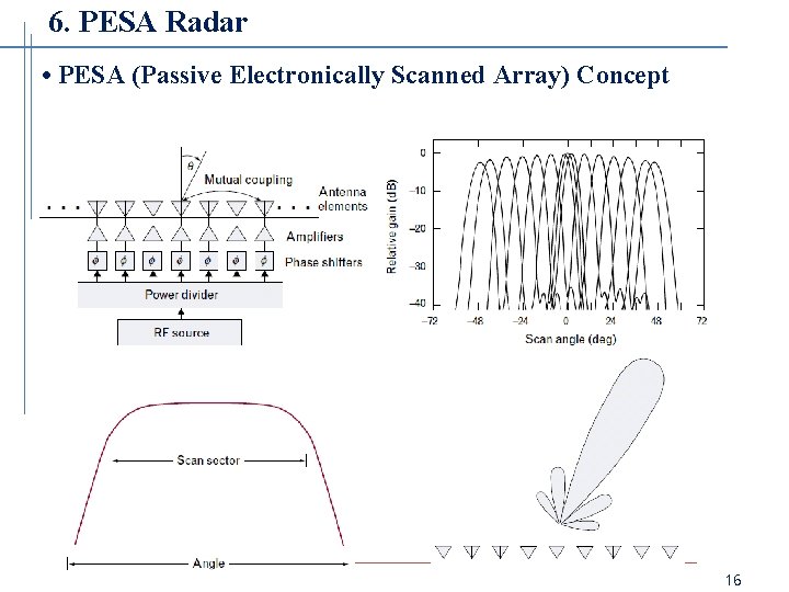
A passive electronically scanned array (PESA), also called a passive phased array, is a radar antenna made of many small radiating elements whose beam is steered, with no moving parts, by setting the relative phase of the signal at each element. The word "passive" describes the face. The elements and the phase shifters behind them do not generate power. The radio-frequency energy is made somewhere else, usually in one high-power tube such as a travelling-wave tube (TWT), a klystron or a crossed-field amplifier, or in a small number of them. It is then carried to the array through a feed, delayed or advanced element by element, and radiated. On receive, the echoes come back through the same phase shifters and are added together in a shared receiver.
That makes a PESA a halfway step between two older ideas. A mechanical radar points one large antenna by turning it. A fully "active" array (an AESA) puts a small transmitter and receiver behind every element. A PESA keeps the single central transmitter of the mechanical radar and takes only the pointing electronic. For about thirty years, from the 1960s to the 1990s, this was the only practical way to build an electronically steered radar that could also handle megawatts or kilowatts of power, and it is still in service in a very large number of ground, ship and air systems.
This article explains the physics from the beginning: why many small radiators form a beam, how a phase gradient tilts it, what limits the scan angle and the bandwidth, and what the real hardware looks like. Then it covers the history, a set of real radars, the strengths and weaknesses, and a side-by-side comparison with the AESA. It is a general technology article. Russian and Soviet radars are used as examples where they are the best examples, and the Cyrillic names appear only there.
Related articles on this site: AESA radar for the other half of the comparison; Don-2N, A-135 / A-235 Nudol and Elbrus for the Moscow missile-defence radar and its computers; 91N6E, S-400, S-300 and S-500 for the air-defence radars; Patriot for the American AN/MPQ-53; Voronezh, Dnepr and SPRN at Solnechnogorsk for early warning; MiG-31 for the first PESA in a fighter; and over-the-horizon radar for a different way of using large arrays.
QUICK FACTS
WHY MANY SMALL ANTENNAS MAKE A BEAM
Every radiating element on its own sends energy out in a very broad pattern, nearly in all directions in front of it. A beam is made by letting the signals from many elements interfere. At a far-away point, the signals from the different elements arrive having travelled slightly different distances. If those paths differ by a whole number of wavelengths, the waves are in step and add up. If they differ by half a wavelength, they are opposite and cancel. Set up properly, the waves add in one narrow direction (the main beam), cancel in most others, and leave small leftovers in between (the sidelobes).
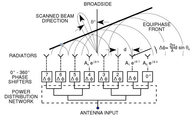
For a straight row of N identical elements spaced a distance d apart and each driven with a phase step of β from one element to the next, the field in a direction θ measured from broadside (straight out of the face) is the sum of N phasors. This sum is called the array factor:
AF(θ) = sum for n = 0 to N-1 of a(n) · exp[ j · n · (2π d / λ · sin θ − β) ]
where a(n) is the amplitude weight on element n and λ is the wavelength. All the terms add exactly in phase, and the pattern peaks, when (2π d / λ) sin θ = β. That is the whole principle. Choose β = 0 and the beam points at broadside. Choose another β and the beam points at
sin θ0 = β λ / (2π d)
For half-wavelength spacing (d = λ/2), this becomes β = π sin θ0. A beam 30 degrees off broadside needs a phase step of 90 degrees from one element to the next; one at 60 degrees needs about 156 degrees. The beam-steering computer calculates one such number for each element, or for each small group, and sends it to the phase shifters. Nothing has to move. A planar array does the same thing in two directions at once, with one phase gradient for azimuth and another for elevation.
The last point is that the array factor is multiplied by the pattern of one element. The pattern of the whole antenna is (element pattern) times (array factor). The array factor makes the narrow beam. The element pattern, which is broad, makes the envelope that the beam sits inside. This product is the reason for scan loss, discussed below.
BEAMWIDTH, GAIN AND THE SIZE OF THE FACE
The width of the main beam depends on how big the array is measured in wavelengths. For a uniformly illuminated row, the half-power beamwidth is about
θ3dB ≈ 0.886 λ / (N d cos θ0) radians, which is roughly 51° divided by (L / λ), where L is the length of the aperture,
and, for half-wavelength spacing, about 102° divided by N when the beam is at broadside. Two things are visible immediately. A longer array makes a narrower beam. And the beam gets wider by a factor of 1 / cos θ0 as it is steered off broadside, because the face looks shorter when seen from the side. At 60 degrees the beam is about twice as wide as at broadside.
Gain follows the effective area. The directivity of an aperture is about 4π A / λ², with A the effective area. With half-wavelength spacing on a square lattice, each element accounts for about λ²/4 of area, so the directivity is roughly π times the number of elements. As a worked example only, an array of 5,000 elements would have an ideal directivity of about 15,700, or about 42 dB, before any of the losses described later. Real gain is lower, and the effective area also shrinks with scan angle, as described next.
A narrow beam is the whole point of a high-gain radar antenna. It concentrates power onto a small patch of sky, which raises range, and it improves angular accuracy and resolution. It also means that to cover a sector, the radar has to point the beam at many positions in turn. The speed at which a phased array can do this is what makes it different from a dish.
WHY STEERING HAS LIMITS: SCAN LOSS
A flat face steered away from broadside has two penalties that add up.
Together these are commonly modelled as a gain loss proportional to cos^1.5 of the scan angle, though the exponent depends on the element design; wide-pattern elements reduce the loss. This is a model and not a law. Textbooks give figures between cos^1 and cos^2.5 depending on whether one counts one way or both ways and on the element. Using cos^1.5 for one-way gain as an illustration: at 45 degrees the loss is about 2.3 dB, and at 60 degrees about 4.5 dB. A radar loses this on transmit and again on receive, so the two-way effect on signal-to-noise ratio is about double, around 9 dB at 60 degrees, in addition to the doubled beamwidth. Typical limits for a flat array are therefore about plus or minus 60 degrees, sometimes quoted as 50 to 70.
That limit explains many designs. A radar that has to see the whole sky is built with several flat faces: four fixed faces on the Aegis ships, four on the building of Don-2N, two on the rotating head of the 91N6E. A fighter nose array covers a cone of about plus or minus 60 to 70 degrees, which is why designers use gimbals or "repositioners" on some arrays to turn the face and extend coverage. The Irbis-E uses exactly this approach: electronic scan of about plus or minus 60 degrees, plus a mechanical drive that moves the face to extend the field of view to about 120 degrees each side (published figures).
GRATING LOBES AND ELEMENT SPACING
The array factor has a repeating nature. For a given spacing, beams of equal strength appear in other directions where the path difference between neighbouring elements is a whole wavelength. These are grating lobes. They waste power, create ambiguous angles and let jammers or clutter in from unwanted directions. They appear when the element spacing is too large for the scan angle.
The condition for no grating lobe to appear anywhere in real space, for a beam scanned to θmax, is
d / λ ≤ 1 / (1 + sin θmax)
For a scan of plus or minus 60 degrees the spacing must be at most about 0.54 wavelength; for plus or minus 90 degrees it must be 0.5 wavelength; for plus or minus 45 degrees about 0.59. This is why "half a wavelength" is the standard number. Triangular (hexagonal) lattices can use somewhat larger spacing for the same scan limit and need about 14 percent fewer elements than a square lattice, which is why they are common.
The rule has to hold at the highest frequency in the band, since the spacing in wavelengths grows as the wavelength shrinks. That is a design limit on the whole bandwidth of the radar. The reverse, the element being too close together, makes mutual coupling worse and increases cost, so designers cluster near half a wavelength.
Quantisation of the phase matters too. A digital phase shifter with n bits steps in increments of 360° / 2^n: 22.5 degrees for a 4-bit shifter, 5.6 degrees for a 6-bit shifter, 2.8 degrees for a 7-bit shifter. Rounding to the nearest step produces small phase errors across the aperture. These raise the average sidelobe level and, in the worst case with a regular pattern of errors, produce "quantisation lobes" of power about 6 dB lower for each additional bit (about -6n dB relative to the main beam). Early radars with 3-bit or 4-bit phase shifters had to live with higher sidelobes; the Patriot AN/MPQ-53 is described with 4-bit ferrite shifters, and AN/SPY-1 moved from 4-bit shifters to 7-bit shifters in later versions (the latter from a Navy technical history). Some arrays randomise the errors across the face to turn quantisation lobes into a low, even floor.
PHASE SHIFTERS: WHERE A PESA SPENDS ITS MONEY
The phase shifter is the central component. Two families matter.
Ferrite phase shifters. A ferrite (garnet) toroid, or a rod, sits in a waveguide. A pulse of current through a wire that threads the ferrite magnetises it to a chosen level, and the magnetisation changes the speed at which the microwave signal travels through it, which sets the phase. Latching types hold the setting with no power until the next pulse. Ferrite shifters handle very high peak power, which is why they sit behind the tube of a PESA. Typical figures from the engineering literature: insertion loss of roughly 0.4 to 1.6 dB over the full range, and switching times of microseconds, perhaps 1 to 100 microseconds depending on design (modern high-current designs under 10 microseconds; older ones 20 to 300). Their weaknesses are weight, cost and the drive electronics. The AN/SPY-1 development team at the Johns Hopkins Applied Physics Laboratory made a particular advance with a garnet ferrite that was far less sensitive to temperature, which mattered for keeping thousands of shifters calibrated.
Diode phase shifters. PIN diodes switch short sections of line in or out. They switch in nanoseconds (roughly 1 to 100 ns in modern designs), are light and cheap, and need only a low-voltage drive. However, they handle much lower power and have more loss per bit, around 0.5 to 1 dB per bit, so a 4-bit device may cost 1 to 2 dB and a 5-bit device 2.5 to 5 dB. Diode shifters therefore appear in lower-power arrays, in the low-power part of an AESA module, and in some PESAs where the power is distributed to subarrays.
In both cases the phase shift is a fixed setting. It does not change with frequency the way a real time delay would. That has a large effect on bandwidth, described in the next section.
Because every element needs its own shifter and drive, a PESA has thousands of them. A Patriot AN/MPQ-53 array is described with about 5,000 ferrite phase shifters (5,161 elements in one source). The AN/SPY-1B/D has 4,350 radiating elements per array, in 2,175 two-element subarrays, with a garnet phase shifter at each element; there are four arrays on a ship. The 91N6E is described in published material as having on the order of 2,700 phase shifters per face; that figure is a published one, as listed in this site's 91N6E article.
TIME DELAY, PHASE AND BANDWIDTH
A phase shifter sets phase, and a time delay sets time. They are equal only at one frequency. To steer a beam properly for a wide-band signal, the element-to-element delay must be a fixed time (about d sin θ / c), which is a different phase at each frequency. With plain phase shifters the phase is fixed, so when the frequency moves away from the design value the beam points somewhere else. This is called beam squint. The relation is f · sin θ0 = (f + Δf) · sin(θ0 + Δθ). For example, at a scan angle of 45 degrees and a frequency change of 5 percent, the beam moves by about 2.7 degrees, which is more than the beamwidth of a narrow-beam radar.
Another way to see it is aperture fill time. A signal sent along the face takes time T = L sin θ / c to cross the aperture; for a 1 metre face at 60 degrees that is about 3 nanoseconds. A signal with a bandwidth wider than about 1/T would be distorted because different parts of the aperture see different parts of the pulse. A common rule is that at wide scan angles the usable fractional bandwidth is about two times the beamwidth in degrees; for a 2 degree beam this is about 4 percent, or about 120 MHz at 3 GHz.
Phase-shifter arrays therefore have limited "instantaneous bandwidth": the width of the signal they can send or receive at once with the beam pointing correctly. The "tunable" or "operating" bandwidth (the range over which the centre frequency can be moved when the shifters are reset) is wider, and the reason a PESA can still frequency-hop pulse to pulse. In the AN/SPY-1, public descriptions mention an instantaneous bandwidth of the order of tens of megahertz in the 3.1 to 3.5 GHz S-band, with measurements over much wider bands.
The cure for squint is true time delay (TTD): switched lengths of line that give a real delay that is the same at all frequencies. TTD units are larger and lossier, so they are used on the sub-arrays of very wide band arrays instead of at every element. Many modern wide-band radars combine phase shifters at each element with TTD at the subarray level. A PESA built on ferrite shifters is, by its nature, a narrow-band to moderate-band device. This was acceptable for tracking and surveillance radars, and it matters more for wide-band imaging and electronic warfare, where AESAs and digital arrays have the advantage.
THE ARCHITECTURE OF A PESA, FROM EXCITER TO ELEMENT
The signal path of a typical PESA on transmit runs: exciter (a stable low-power source and waveform generator) → driver stages → high-power amplifier (tube) → duplexer or circulator → feed network → phase shifters → radiating elements. On receive it runs in reverse: element → phase shifter → combining network (which also forms the sum and difference channels used for monopulse angle measurement) → duplexer and receiver protector → low-noise amplifier → down-conversion and digital processing.
The transmitter. Early PESAs used one big tube or a few. The travelling-wave tube is an amplifier with a wide bandwidth, good gain and the ability to transmit a programmed waveform, which is why it became the standard. Klystrons are more powerful and efficient at a fixed frequency; crossed-field amplifiers (amplitrons) were used where lots of peak power and efficiency were more important than gain. Some designs gang several tubes together. As an example, the AN/MPQ-53 uses a TWT-based transmitter with upgrades adding a second TWT (published description), the Irbis-E uses a pair of 10 kW tubes for 20 kW peak (published description), and the AN/FPS-108 Cobra Dane is described with 96 TWTs in 12 groups of eight, each rated roughly 175 kW peak. At the other end of the range, the Moscow-area radars described on this site used much larger devices for megawatt pulses.
A useful way to compare architectures is to divide the peak power by the number of elements. For the Irbis-E, 20,000 W over 1,772 elements is about 11 W per element, before any losses. This is about the same order as the per-module power of a modern X-band AESA. The two designs do not differ because one has more peak power; they differ in where the power is made, how much of it survives to the antenna, and how flexibly it can be controlled.
The feed. The feed carries the transmitter's power to every element and collects the received signal. Two families exist.
A space-fed array is still passive. Nothing in the lens produces power. It only imposes phase on a wave that the central tube already made.
Subarrays. Between a single tube and a tube per element there is a middle path. In arrays of subarrays, each group of 32 or 64 elements gets its own tube or feed, and the phase shifters work inside the group while time delay or phase control works between the groups. The AN/SPY-1 was developed from the APL AMFAR demonstrator, which proved the idea of a subarray (say 64 elements) fed by a high-power microwave tube, so that very high total power could be made without any single tube producing it all. Public descriptions of how many transmitters the SPY-1A has differ: a 1977 US Naval Institute article describes two transmitters, forward and aft, while a later reference describes eight transmitters each with four 132 kW crossed-field amplifiers driving transmit subarrays. I have left the numbers out of the comparison because the sources disagree and the design changed between versions.
Receive. On receive there is generally one sum channel and two difference channels (azimuth and elevation) for monopulse measurement, and sometimes a guard or sidelobe-cancelling channel. The small number of receive channels is a defining PESA feature. It means the radar has one view of the world at a time, and a beam is formed by the analogue feed. Some hybrid radars add receive channels or low-noise amplifiers at the subarray level; the Bars and Irbis-E families are described as hybrid designs with several receive channels, but their transmit side is still a passive tube-fed array.
LOSSES: WHY THE FEED MATTERS TWICE
In a PESA all the power travels through the phase shifters and the feed on the way out, and all the weak echo travels back through them on the way in, before it reaches a low-noise amplifier. Every decibel of loss is paid twice.
A worked example with round numbers (illustrative, not any specific radar): suppose the phase shifter, feed and duplexer have a total of 3 dB loss each way. On transmit, only half the power reaches the sky. On receive, a 3 dB loss ahead of the amplifier is the same as raising the system noise by 3 dB. Both effects reduce the signal-to-noise ratio, a total of 6 dB. Because radar range varies as the fourth root of the signal-to-noise ratio, a 6 dB loss reduces range by a factor of about 0.71, around 29 percent shorter. The published ferrite figures of 0.4 to 1.6 dB per shifter show that this is not an exaggeration, especially once the long waveguide runs, the combiner and the duplexer are added.
An AESA avoids most of that. It places the power amplifier and the low-noise amplifier right behind the element so the long lossy path has little effect. Carlo Kopp, writing in 2002, estimated that having the low-noise receiver within the antenna cuts receiver thermal noise by a factor of two to four, and noted that the ferrite shifters of earlier passive arrays made them less sensitive than the mechanically steered antennas they replaced, which was compensated by more powerful tubes. The same loss is the reason that the PESA keeps the high-power tubes: it needs the power to overcome its own feed.
Power handling and cooling. The feed also has to carry the tube's full peak power without arcing, which requires large waveguide, sometimes pressurised, and careful design of every joint. The heat, though, is concentrated at one or a few points (the tubes and their power supplies), which is simpler to cool than thousands of small amplifiers spread over the face but means that the tubes need high-voltage supplies, which are heavy and a reliability concern.
HOW A PESA SEARCHES, TRACKS AND GUIDES AT ONCE
The main operational gain of a PESA over a dish is beam agility. A computer decides, pulse by pulse or dwell by dwell, where the next beam goes, how long it dwells and what waveform it carries. The beam can jump from one end of the sector to the other in the time it takes to reset the phase shifters: a few microseconds for modern ferrite shifters, tens to hundreds of microseconds in older ones. Published figures for the radars below are of that order: 1.2 milliseconds for the beam positioning of the Zaslon, 400 microseconds for the N011M Bars. A dish takes seconds.
Agility allows time-sharing. The radar divides its time into short slices. In one it searches a sector, in another it fires a confirmation beam at a new detection, in a third it tracks a known target, and in a fourth it sends an uplink to a missile in flight. All of this is interleaved so quickly that every function seems to run at once. Patriot's AN/MPQ-53 is a standard example: it is described as performing surveillance, tracking, missile guidance and electronic-protection functions in a time-shared way, with the computer building action cycles lasting milliseconds, with up to 32 radar configurations and 54 operational modes (published descriptions). AN/SPY-1 does the same at sea: its 1977 description states that instead of painting a target once per rotation, the radar uses hundreds of pencil beams, and when a detection occurs the computer schedules several more dwells on that target within a second, creating a track in less time than it takes a rotating radar to complete one turn.
Notice the limit, though. At any instant a PESA transmits one beam with one waveform. Time-sharing hides this, but it takes real time from the radar's budget. If a radar spends 40 percent of its time tracking and guiding, that time is not spent searching. An AESA, which can split its face into groups and send different beams with different waveforms at the same instant, can use the same face for several jobs concurrently; see the AESA article.
HISTORY: FROM BRAUN TO AEGIS
Also worth knowing: the AN/FPS-115 PAVE PAWS, from the late 1970s, used solid-state transmit-receive modules (1,792 active per face) and so is an early active array, not a PESA. The "PESA era" and the "AESA era" overlapped for decades.
HARDWARE FAMILY TREE: WHERE "PASSIVE" ENDS AND "ACTIVE" BEGINS
It is helpful to see the designs as a spectrum of how far the power is distributed.
The usual dividing line is whether there is a transmit amplifier at or immediately behind the radiating element, along with a receive amplifier, so that the power is made in the aperture and not fed to it. By that test, tube-fed subarrays count as passive and a transmitter per element counts as active, and the big-module arrays fall in between. A design can be argued either way, and an honest article should say so. The Don-2N article on this site does so explicitly.
SOVIET AND RUSSIAN PESA RADARS (Радары с пассивной фазированной антенной решёткой)
Russia and the Soviet Union built many PESAs, because they had mature tube and ferrite technology before solid-state modules were available at scale, and some of the systems are still in production.
Заслон (Zaslon, N007; NATO Flash Dance). The radar of the MiG-31 interceptor, developed from 1975 to 1980 at the Tikhomirov research institute (НИИП, NIIP). It is a pulse-Doppler X-band radar with a PESA antenna, a diameter of about 1.1 m (some sources say 1.4 m), a fixed face with a published scan sector of about plus or minus 70 degrees in azimuth and +70/-60 degrees in elevation. The published description lists about 1,700 X-band emitters and 64 L-band emitters (for the identification transponder) in the same antenna, ferrite phase shifters with a beam-positioning time of about 1.2 ms, detection of a 16 square metre target at 200 km, and the ability to track 10 targets and engage four (Rosoboronexport catalogue, via Wikipedia). It was the first PESA fitted to a jet fighter. The MiG-31 is described in this site's MiG-31 article.
Барс (Bars, N011M). A hybrid PESA for the Su-30 family. Published figures: a slotted-array antenna about 960 mm in diameter, peak power of 4 to 5 kW and average about 1.2 kW, a beam-positioning time of 400 microseconds, and a fixed-face scan sector of about plus or minus 70 degrees in azimuth and plus or minus 45 in elevation, extended to about 90 degrees by mounting the antenna on a mechanical drive. It builds on the Zaslon experience.
Ирбис-Э (Irbis-E, N035). An X-band hybrid PESA for the Su-35, developed from the Bars. Published figures: a 900 mm antenna with 1,772 radiating elements, two 10 kW tubes for 20 kW peak and about 5 kW average, electronic scanning of about plus or minus 60 degrees plus a mechanical drive extending the total field of view to about 120 degrees, detection of a 3 square metre target at up to 400 km in a narrow search sector (200 km otherwise), tracking of up to 30 targets and attack on up to 8 (NIIP product data as reported). Whether the 400 km figure holds in service is not independently verified, and it is a manufacturer's number.
91Н6Е and 92Н6Е (91N6E, 92N6E). The S-400's acquisition radar and engagement radar. The 91N6E is a rotating, space-fed, dual-face reflection-type PESA in the S band (the "Big Bird") and the 92N6E is an X-band phased-array engagement radar. Details are in the 91N6E and S-400 articles. Both are tube-fed passive arrays by the descriptions on this site.
30Н6 (30N6) and the S-300 family. The engagement radars of the S-300 are described by the Microwave Journal's history as PESAs with passive optical space feed, transmissive ferrite arrays and TWT transmitters, similar in design approach to Patriot's AN/MPQ-53. See S-300.
Дон-2Н (Don-2N). The Moscow ABM radar at Sofrino. Here the sources disagree, and the disagreement is instructive. Some Western sources, and an earlier version of this very article, listed it as a PESA. Russian developers describe it as a large-aperture active phased array in which the transmit power is generated within the antenna: a memoir by the head engineer of the manufacturing plant at Dnepropetrovsk states that Don-2N adopted the "active phased array with power distributed in the aperture" model, with megawatt-class transmit modules of about 300 kg each, tens of them per face. That is neither a single-tube PESA nor a modern AESA with thousands of small modules. The module count is not public. The Don-2N article gives the full account and takes the reading "active, large-module". This article follows that reading and does not list Don-2N as a PESA. The real lesson is that "passive" and "active" are the ends of a range and that big-module arrays sit between.
Воронеж (Voronezh). The current family of Russian early-warning radars. Descriptions in sources differ: some call the arrays active phased arrays, while a technical reference for the Voronezh-DM describes a passive phased array with transmit power from air-cooled disk triodes at around 470 MHz. This article does not settle it. The Voronezh article on this site uses a hedged description. The older Dnepr radars are a different principle again: they steer in azimuth by changing the frequency of the transmitted signal, not by phase shifters. The SPRN at Solnechnogorsk article describes how their data are used.
Резонанс-Н (Rezonans-N). A metre-band (VHF) surveillance radar with a phased antenna array designed to detect low-observable aircraft; the sources I found do not state whether the array is passive or active, so it is mentioned here only to show that the choice of band matters as well as the choice of architecture.
Chinese and Japanese examples. China's KLJ-3 (Type 1473) fighter radar on the J-10B is listed in the sources I found as a PESA, while the J-20's Type 1475 and the Type 346 naval radar are AESAs. Japan's OPS-24 is listed as the first serially produced shipborne AESA, and Japan's F-2 fighter carried the J/APG-1, described as the first AESA on a combat aircraft (1995). I did not find reliable, detailed public specifications for Chinese or Japanese PESAs, so I give no numbers for them. Both countries moved to active arrays early compared with Russia.
WHAT A PESA IS USED FOR
ADVANTAGES OF A PESA
LIMITS OF A PESA
PESA VERSUS AESA, SIDE BY SIDE
The full comparison is in the AESA article. The main points in short form:
WHICH IS BETTER, AND WHEN
An AESA is better for almost any new fighter, ship or air-defence radar. It is more reliable, can do more at once, and its costs have come down. A PESA still makes sense in a few cases: when an existing design is mature and cheap, when very high peak power at lower frequency is needed and a tube is the simplest way to get it, and when the cost of a new radar is not justified by the gain. Many of today's PESAs were designed in the 1970s to 1990s and have been upgraded in processing and software to stay useful.
The decision is not just a technology one. A radar that meets the requirement and can be built and maintained with the country's industry has value. A technically superior radar that cannot be made in quantity does not.
COMMON MISTAKES AND MYTHS
WHAT IS UNCERTAIN IN THIS ARTICLE
IN ONE SENTENCE
A PESA radar steers its beam by setting a computer-controlled phase at each element of a flat array fed from one tube transmitter, so it gets microsecond beam agility and very high peak power without moving the face, at the price of feed losses, one waveform at a time, limited bandwidth and a single transmitter that can take the whole radar down.