WHAT IT IS
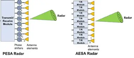
An active electronically scanned array (AESA), also called an active phased array, is a radar antenna in which every radiating element, or a small group of elements, has its own transmit/receive (T/R) module. The module contains a power amplifier for transmit, a low-noise amplifier for receive, a phase shifter, usually a gain (amplitude) control, and a switch that connects the element to one or the other. "Active" means that the face itself makes the radio-frequency power. A PESA face only shifts the phase of power that arrived through a feed from a central tube. An AESA face is a wall of hundreds or thousands of small radars working together under one beam-steering computer.
The beam is still formed by the same interference principle as in a PESA: a phase gradient across the face tilts it, and the same relations for beamwidth, scan loss and grating lobes apply. If you have not read the PESA article, its first sections explain that physics in detail, and this article assumes it. What changes in an AESA is where the power is made, where the first receive amplification happens, and how much of the beam-forming can be done in software. Those three changes account for almost every advantage, and almost every cost, of the AESA.
This is a general technology article. Western, Chinese, Japanese and Russian examples are all used. Russian and Soviet radars are mentioned where they illustrate a point, and Cyrillic names appear only there.
Related articles on this site: PESA radar for the passive counterpart; Don-2N, A-135 / A-235 Nudol and Elbrus for a Russian large-module array and its computers; 91N6E, S-400, S-300 and S-500 for Russian air-defence radars; Patriot for the AN/MPQ-53 PESA whose successor, LTAMDS, is an AESA; Voronezh, Dnepr and SPRN at Solnechnogorsk for early warning; MiG-31 for the first fighter PESA; and over-the-horizon radar.
QUICK FACTS
THE T/R MODULE
A typical X-band fighter module is a few centimetres across and weighs a few tens of grams. The published transmit chain is: digital phase shifter (often 6 bits, steps of 5.6 degrees) → gain control (for amplitude taper and sidelobe control) → driver → high-power amplifier (HPA) → circulator → element. The receive chain is: element → circulator → limiter (protects the receiver from a strong signal) → low-noise amplifier (LNA, noise figure often of the order of 2 to 3 dB at X-band) → receive-side phase and gain control → combining network → digital receiver.
Because the phase shifters sit before the power amplifier on transmit and after the LNA on receive, they only handle low power. That lets designers use small semiconductor switches instead of ferrite, and switching takes nanoseconds, not microseconds. Switching a module between transmit and receive takes tens to a few hundred nanoseconds, which is what lets one face interleave search, track, illumination and, on some sets, communications or electronic attack.
Packaging. Modules may be one per element, or "quads" with four channels in one block. A published description of the Phazotron Zhuk-AE prototype gives 575 mm aperture and 680 modules, while older descriptions say 652 channels in 163 quad modules; I give both because the sources differ, and the counts are for different builds or counted differently.
What a module costs. Carlo Kopp, writing in 2002, said a fighter radar needed typically between 1,000 and 1,800 modules, that early module builds cost on the order of US $2,000 each, and that this made the radar cost prohibitive unless unit costs fell to hundreds of dollars. Costs have since fallen with volume and with the commercial use of the same chips. Those are early-2000s figures, not current ones.
Efficiency. A T/R module's transmit efficiency is typically below 45 percent according to Kopp (2002); published X-band GaN amplifier designs report power-added efficiency in the range of about 40 to 56 percent. The rest is heat, and heat is the dominant engineering problem of an AESA.
GALLIUM ARSENIDE AND GALLIUM NITRIDE
First-generation fighter AESAs used GaAs monolithic microwave integrated circuits (MMICs). GaN transistors, which have a wider bandgap, take higher voltage and carry more power per unit of transistor width. Published comparisons for X-band amplifiers give about 4 to 8 watts per millimetre of gate width for GaN against about 0.5 to 1.5 for GaAs, so about five times more power density is a reasonable practical figure; claims of ten times are not generally supported. GaN is usually built on silicon carbide, which also spreads heat better.
What that gives a designer is a choice. The same area can give more power per module, or the same power can come from a smaller or fewer modules, or the same module can run cooler. What it does not give is a free reduction in heat: GaN efficiency at X-band is often only modestly better than GaAs, and smaller, hotter transistors concentrate the heat flux, so low-void die attach, good baseplate materials and effective cooling matter more.
Examples of the shift: the AN/SPY-6 ship radar is built on GaN; the AN/TPY-2 missile-defence radar was built with GaAs modules, and GaN retrofits followed, with seven GaN-based radars produced in 2020 and the first radar delivered to the US Missile Defense Agency with a fully GaN-populated array in May 2025 (manufacturer and trade-press statements); the Eurofighter's ECRS Mk1 radar uses GaN while the Mk0 used GaAs, and the Mk2 combines GaAs and GaN (as described in Leonardo and trade material); the French RBE2-AA is a GaAs AESA with a GaN successor planned (RBE2-XG).
COOLING, POWER AND WEIGHT
An AESA has to remove all the heat that its amplifiers do not turn into radio waves. As an illustration only (round numbers, not any specific radar): 1,500 modules at 10 W peak each is 15 kW peak. At a 20 percent duty cycle, the average radio-frequency power is 3 kW. If the modules are 30 percent efficient, they draw 10 kW of direct current and turn 7 kW into heat, in a flat plate a fraction of a square metre in size. Air cooling is not enough at that density, so airborne and ground AESAs of military duty cycle use liquid cooling: US designs have used a synthetic oil-like coolant called polyalphaolefin, and the heat is passed to a heat exchanger or, on aircraft, to fuel. That requires pumps, plumbing, heat exchangers, and electrical power, and it adds weight. The same radar would need power for a tube-based design too, but the AESA's heat is spread over thousands of points on the face.
Kopp summed it up as a trade: compared with an air-cooled conventional radar, an AESA is more reliable but needs more electrical power and cooling, and can usually transmit much more power if required, although more power makes the radar easier for an enemy receiver to detect.
On the other side of the ledger, the AESA gets rid of the high-voltage tube, the high-voltage power supply, and the pressurised waveguide that carries the tube's power to the antenna. Each module runs from a low-voltage supply (a few volts, not kilovolts), and handles only a few watts, so it can be designed for much lower electrical stress.
DISTRIBUTED TRANSMIT AND RECEIVE
In an AESA the amplification is at the element. On transmit, hundreds or thousands of small amplifiers radiate their signals, which add in the air. On receive, the weak echo meets a low-noise amplifier almost immediately, with only a short, low-loss path before it. System noise is therefore set by the module's LNA, not by metres of lossy waveguide and phase shifters. In the PESA article the worked example shows that 3 dB of loss each way costs about 29 percent of the range; the AESA avoids most of that. Kopp estimated that putting the low-noise receiver in the antenna cuts the receiver's thermal noise by a factor of two to four.
The feed to the array carries only low-level signals and direct current, so the long, pressurised, high-power waveguide of a PESA is not needed. It also means that the array can be thin and can be built as flat panels or "tiles," which is useful for aircraft noses and for ship faces built from standard modular blocks. The AN/SPY-6(V)1, for example, uses four fixed faces, each built from 37 "radar modular assemblies," each a self-contained radar of about 2 by 2 by 2 feet, and the Navy describes the radar as about 30 times more sensitive than the AN/SPY-1 (a figure of about 15 dB, or the ability to detect a target half the size at twice the range).
DIGITAL BEAMFORMING
A basic AESA still forms its beams in analogue form: the phase and gain settings combine the signals from all modules into one sum signal (and difference signals for monopulse). A step further is digital beamforming (DBF), where the signal is digitised at the module or at a subarray, and the beams are then formed by processing in software.
The public sources I found for the AN/SPY-6 support digital beamforming and a modular RMA/subarray architecture, with multiple simultaneous beams, but they do not settle whether the signal is digitised at every element or at the subarray level; I have not assumed one. Kopp noted in 2002 that the AN/APG-77 was the first of a new generation of radars that moved back-end signal and data processing out of a dedicated radar box and into the aircraft's central computers.
Digital beamforming also makes possible adaptive processing. The radar can calculate where a jammer is coming from and put a null (a deep notch in the receive pattern) in that direction, while keeping the gain on the rest of the sky. It can compensate for broken modules by recalculating the weights. And it makes the radar an upgradeable software-defined system. Kopp noted that over the life of an AESA, refinements can be added as software upgrades.
MANY BEAMS, MANY JOBS
In a PESA, all elements radiate the same pulse at the same time, so only one beam with one waveform exists at an instant. In an AESA, each module is independently controlled in amplitude and phase, and can be given its own signal. Several things follow.
LOW PROBABILITY OF INTERCEPT, WAVEFORM AGILITY AND FREQUENCY HOPPING
A radar warning receiver on an enemy aircraft can detect a radar at much greater distance than the radar can detect the aircraft, because the signal only has to travel one way. A low-probability-of-intercept (LPI) radar tries to make itself hard to detect and recognise. An AESA helps in several ways.
LPI is a matter of degree. Modern receivers designed to detect LPI signals exist, and a radar that must reach far still has to put power out. Raising the transmit power to increase range also makes the radar easier to detect, as Kopp noted.
GROUND MAPPING, SAR AND GMTI
Imaging modes use the radar's wide bandwidth and its ability to hold a stable phase while the aircraft moves. Synthetic aperture radar (SAR) builds a map of the ground by combining echoes from many positions along the flight path; ground moving target indication (GMTI) picks out vehicles moving against the background of ground clutter. Both put demands on the radar: stable phase, wide bandwidth, accurate beam pointing, and the ability to switch between mapping and air-to-air search quickly.
AESAs suit these modes because beam agility lets the radar interleave mapping with air search; the radar can lay out mapping strips and spot-lights while still looking for threats. Wide instantaneous bandwidth is easier with solid-state modules and, where needed, true time delay at the subarray. Public material describes SAR modes in the Irbis-E, which is a PESA (with limited SAR resolution according to one source), so these modes are not exclusive to AESAs. They are easier, more flexible and better in an AESA. Kopp's 2002 survey also noted the planned replacement of the passive array on the E-8 JSTARS surveillance aircraft with an X-band AESA, and lists L-band AESAs such as the one on the RAAF's Wedgetail airborne early warning aircraft.
GRACEFUL DEGRADATION AND RELIABILITY
The most cited operational benefit of the AESA is how it fails. In a PESA the failure of a tube or its supply loses the face. In an AESA, power and receive gain are spread over a thousand or more modules, so no single failure matters much.
Published analysis gives some numbers. For a large array, random failure of 10 percent of the modules reduces the coherent gain by about 0.8 to 0.9 dB one way. This agrees with simple arithmetic, since the field from 90 percent of the elements is 0.9 of the full amplitude, and 20 times the base-10 logarithm of 0.9 is -0.9 dB. A 2023 study evaluated failure rates of 5 to 10 percent against mission detection requirements. But the same literature warns that "graceful" is conditional: with only a few percent random failures, the sidelobes at some angles can rise by several decibels, enough to let clutter in, and a failure of modules that is clustered rather than random hurts more. Kopp said failure of up to 10 percent of the modules will not cause loss of the antenna function, only degrade it, and that a radar that has lost several modules can be operated until a scheduled maintenance period.
On reliability in general, Kopp cited typical mean time between failures (MTBF) of conventional mechanically scanned fighter radars of 60 to 300 hours, against 1,000 hours or better for an AESA, which at 200 flying hours a year is a repair every five years or so. That is a 2002 comparison of fighter radars and a general figure, not a measurement of any one set. Part of the difference is the removal of the tube, the high-voltage supply and the mechanical gimbal, which wears out.
ELECTRONIC ATTACK
Because an AESA can form narrow, high-gain beams quickly and generate arbitrary waveforms, it can be used as a jammer. It can aim noise or false-target signals at an enemy radar's direction with much more effective power than an omnidirectional jammer, because the full gain of the aperture is used in a narrow beam. This is sometimes called "beam jamming" or "targeted electronic attack". In US public sources, the F-35's AN/APG-81 is described as able to use its array for targeted electronic attack together with the AN/ASQ-239 suite, and the F-22's AN/APG-77 as an LPI radar with jamming capability. Open commentary also discusses delivering cyber effects through a radar's radio link; that is speculative in public material and I do not rely on it.
The limit is power and heat. A radar module is designed for pulsed duty cycle at one band. Sustained jamming over wide bandwidth and many beams uses power and cooling that the aircraft also needs for other purposes.
GEOMETRY THAT DOES NOT CHANGE
Several limits come from the physics of a flat array, not from the power source, and an AESA has them all.
AESA EXAMPLES
United States.
Europe.
Asia.
RUSSIAN AESA DEVELOPMENT (Российские АФАР)
The Soviet Union and Russia built mature PESAs, and came late to active arrays at fighter scale. Carlo Kopp wrote in 2002 that the Russians "remain in the passive AESA domain" and expected that to change as GaAs chips became available; the actual change took longer.
Жук-АЭ (Zhuk-AE) and its successors. Phazotron's X-band AESA for the MiG-35. A prototype with a 575 mm aperture and 680 modules is described flying on a MiG-35 in 2009; its published flight-test detection ranges were about 148 km forward and 60 km to the rear, and not the 160 km that is sometimes quoted. The production-intent Zhuk-AM/AME is described with about 1,000 modules and advertised at 160 to 200 km, with later claims of more. I could not identify a Phazotron radar called "Gryphon" in the sources I found, so I do not include one.
Белка (N036 Byelka). The Su-57's radar suite by Tikhomirov NIIP: one X-band N036-1-01 array in the nose, two X-band N036B-1-01 arrays on the sides, and two L-band N036L-1-01 arrays in the wing leading edges for identification and electronic warfare. Reported module counts differ between sources: 1,514 in the nose and 404 in each side array in one, 1,552 and 358 in another. A report in November 2021 quoted the NIIP director general as saying the Su-57 AESA had yet to pass its debugging phase. The Su-57's radar status is therefore partly open, and the numbers above should be read as reported figures.
Ирбис-Э (Irbis-E). A PESA, not an AESA, in spite of being newer than some AESAs. See the PESA article.
Don-2N, 91N6E, 92N6E. Don-2N is described by its Russian designers as an active large-module array, not a PESA, but that is a long way from a modern AESA with thousands of small modules; the Don-2N article has the full account. The 91N6E and 92N6E of the S-400 are PESAs. Voronezh (Воронеж) early-warning radars have been described as active in some sources and as passive in at least one technical reference; I have not settled the question. See Voronezh. The Резонанс-Н (Rezonans-N) metre-band radar has a phased array whose active or passive type was not stated in the sources I found.
Russian GaN. Russia has active GaN work, but the evidence I found is for components and foundries, not for a confirmed fielded Russian AESA with GaN modules. NIIET is described as the only domestic serial supplier of GaN RF transistors, aimed at radar, navigation and communications; Istok is reported to be developing a 0.25 micrometre GaN-on-silicon-carbide MMIC process; and TUSUR and Reshetnev are reported to have built AESA T/R modules and power amplifiers for new-generation communication systems, with production planned for 2028. A published account of Tikhomirov's AESA work described GaAs, not GaN. Dependence on imported parts has been a recurring theme in outside commentary, but I have not found a reliable source for the current state of that dependence, so I do not state one.
AESA VERSUS PESA: THE DIFFERENCES, ONE BY ONE
The following is the full comparison in prose. Where a number is given it is a general figure or an example, not a rule.
WHICH IS BETTER, AND WHEN
For a new fighter, ship, or air-defence radar the AESA is the default, since it does more, lasts longer in service and gets better with software. The PESA still has a case in four situations. The first is an existing mature design where the cost of a new radar would not be justified. The second is a very high peak-power requirement at lower frequencies, where a tube is the simplest way to get it. The third is a country without an industrial base for modules in volume. The fourth is a design where the extra capabilities of the AESA would not be used.
Radars of both types remain in service side by side. The S-400's 91N6E and 92N6E are PESAs; the Su-57's Byelka is an AESA; the Patriot's AN/MPQ-53 is a PESA that LTAMDS is replacing with an AESA. A PESA is not obsolete because an AESA exists. It is a different set of trade-offs.
COMMON MISTAKES AND MYTHS
THE FUTURE
Everything in this section is a trend, not a guarantee.
WHAT IS UNCERTAIN IN THIS ARTICLE
IN ONE SENTENCE
An AESA radar is a phased array whose beam is still a phase gradient across a flat face, but whose power and first-stage receive amplification are made in hundreds or thousands of small transmit/receive modules at the elements, which is why it can fail one module at a time, form several beams and waveforms at once, resist detection better, and do jobs such as jamming or imaging that a single-tube PESA cannot, at the price of heat, module cost and cooling.