WHAT THEY ARE
Cutler (call sign NAA, 24.0 kHz) in Maine and Jim Creek (call sign NLK, 24.8 kHz) in Washington State are United States Navy very-low-frequency (VLF) radio stations. Their job is to put a continuous, encrypted, one-way broadcast on the air that a submarine can receive while it is still underwater. Cutler serves the Atlantic and Arctic; Jim Creek serves the Pacific. Both are among the most powerful radio transmitters ever built, and both are physically enormous because the physics of VLF forces them to be. [DOCUMENTED]
This page explains the whole chain, from the physics of why 24 kHz goes through seawater at all, to why a station that radiates about a megawatt needs a peninsula of antenna wire, to how a few hundred bits per second reach a submarine thousands of kilometres away, to what happens if the stations are lost. It also covers the airborne backup (the E-6B Mercury, "TACAMO"), the extremely-low-frequency (ELF) system the Navy used to run, and the other VLF stations around the world. Where a number comes from the Navy's own documents it is labelled as such; where it is the author's calculation from standard physics it is marked as an estimate; where sources disagree, the page says so.
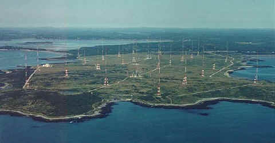
The one-paragraph version. A ballistic-missile submarine is safe only while nobody knows where it is. It must therefore stay deep, stay quiet and stay silent, and it must still be reachable by the national command authority at any time. Radio at ordinary frequencies cannot go through more than a fraction of a metre of salt water. Radio at 15 to 30 kHz can, to a depth of roughly ten to twenty metres, which is enough for a submarine trailing a buoyant wire near the surface. Radio at around 76 Hz (ELF) can go much deeper but carries almost no information. So the Navy built a layered system: VLF for a real (if slow) text broadcast, ELF as a bell-ringer, and an aircraft with a five-mile trailing wire as the survivable backup. Cutler and Jim Creek are the two big fixed VLF stations in the continental United States.
HOW TO READ THIS PAGE
Important claims carry a label:
Nothing on this page gives access information for any station. The stations are Navy installations. Cutler and Jim Creek are fenced, guarded, and not open to visitors without authorisation, and nothing here is meant to help anyone approach them.
THE SYSTEM END TO END
It helps to see the whole path once before looking at its parts. The 1990s Navy document that describes the system in the most detail (the Submarine Communications Master Plan, published by the Federation of American Scientists) gives this outline, and its structure has not changed in principle. [DOCUMENTED, but the document is about thirty years old, and details of today's equipment are not public]
The rest of this page follows that path, but starts where the physics starts: with the seawater.
WHY VLF: THE SEAWATER PROBLEM
Seawater is a conductor. It contains about 3.5 percent dissolved salt, mostly sodium and chloride ions, and its conductivity is about 4 siemens per metre (it varies with temperature and salinity, roughly 3 to 5). That is poor compared with copper (about 60 million S/m) but, for radio waves, it is a very good conductor indeed, because a radio wave is a rapidly alternating electric field and the question is how fast the free charges can respond compared with the field alternation.
Compare the two currents a wave drives in a medium. The conduction current density is sigma times E. The displacement current density is omega times epsilon times E, where omega is 2 pi f and epsilon is the permittivity. For seawater, epsilon is about 81 times the permittivity of free space. At 24 kHz the ratio of conduction to displacement current is sigma / (omega epsilon) = 4 / (2 pi x 24,000 x 81 x 8.85e-12), which is about 37,000. [ESTIMATE] So the seawater behaves almost entirely as a conductor at VLF. (The two currents only become equal at about 900 MHz, which is why microwaves behave differently.) In a good conductor a plane wave does not propagate in the ordinary sense. It diffuses, and it decays exponentially with depth.
Skin depth. The depth at which the wave amplitude falls to 1/e (about 37 percent, or 8.7 dB) is the skin depth:
delta = 1 / sqrt(pi f mu sigma)
where mu is the permeability of free space (4 pi x 10^-7 H/m). For seawater with sigma = 4 S/m, the author's calculation gives:
| Frequency | Skin depth in seawater (sigma 4 S/m) | Attenuation in dB per metre | Comment |
|---|---|---|---|
| 76 Hz (ELF) | about 29 m | about 0.3 | hundreds of feet usable |
| 3 kHz | about 4.6 m | about 1.9 | bottom of VLF |
| 10 kHz | about 2.5 m | about 3.5 | |
| 24 kHz | about 1.6 m | about 5.4 | Cutler and Jim Creek |
| 100 kHz | about 0.8 m | about 11 | LF |
| 1 MHz | about 0.25 m | about 35 | medium wave |
| 10 MHz | about 0.08 m | about 110 | HF, effectively opaque |
[ESTIMATE, from the standard skin-depth formula. Published sources quote "about 2 m" at 15 to 24 kHz, which agrees.]
The attenuation in decibels per metre is 8.686 divided by the skin depth. At 24 kHz that is about 5.4 dB per metre. Ten metres down the signal has lost about 54 dB, twenty metres about 107 dB, thirty metres about 160 dB. A loss of 107 dB means the field is about a hundred-thousandth of its surface value. That is why the practical limit for a plain VLF receive antenna in the water is on the order of ten to twenty metres, and why sources typically quote "about 20 metres" for the maximum. [ESTIMATE for the dB figures; the "about 20 m" is a commonly quoted working figure, SINGLE-SOURCE in that this was not independently checked]
Fresh water (about 0.003 S/m) is a poor conductor by comparison and its skin depth at 24 kHz is about 60 m, which is why some inland freshwater experiments behave differently.
The wave in the water. Inside the conductor the wavelength is not 12.5 km any more. It is 2 pi times the skin depth, about 10 metres at 24 kHz, and the wave travels at only about 245 km/s (omega times delta). [ESTIMATE] This enormous change of wavelength is the reason the transmitted wave bends so strongly at the surface: whatever the angle at which the wave strikes the sea, the refracted wave inside the water travels almost exactly straight down. A submarine therefore sees the field as a nearly horizontal electric and magnetic field of the wave descending vertically through it, whatever direction the transmitter is in. That has a consequence for antenna design. The wave in the water has its electric field horizontal, so the only useful antennas are horizontal ones: a horizontal wire or electrode pair that picks up the electric field by conduction, or a horizontal loop that picks up the magnetic field by induction. A classic 1958 paper in IRE Transactions on Antennas and Propagation (cited in the sources) analyses exactly this.
Why not simply go lower? A lower frequency penetrates deeper (skin depth goes as one over the square root of frequency). At 76 Hz the skin depth is about 29 metres, so a submarine could be hundreds of feet down. But three costs rise sharply as frequency falls: the antenna must be longer for the same radiated power, the available bandwidth (and therefore the data rate) falls in proportion, and the signal-to-noise ratio gets worse at the very lowest frequencies. The ELF system the Navy ran at 76 Hz carried about one character per minute. VLF at 15 to 30 kHz sits at a compromise: enough penetration for a boat near the surface, enough bandwidth for tens of bits per second per channel, an antenna that can (just) be built, and a propagation path with low loss around the world.
Why not go higher? HF (3 to 30 MHz) would offer far more bandwidth and a normal-sized antenna, but a submarine would have to be at periscope depth, or have an antenna mast above the surface, to receive it. A submarine at periscope depth with an antenna in the air is exposed to aircraft, satellites and ships, and it must be slow. A boat that can hear the shore without ever coming up is the entire point.
THE EARTH-IONOSPHERE WAVEGUIDE
At HF the wave is reflected by the ionosphere at a particular height and returns by a few discrete hops. At VLF the wavelength (10 to 20 km) is comparable with the height of the lower ionosphere (about 60 to 90 km), and a different picture applies. The space between the conducting Earth surface and the conducting lower ionosphere acts as a waveguide, a parallel-plate guide wrapped around the planet. The seawater below and the D-region of the ionosphere above both reflect VLF waves strongly, so the energy is trapped in the shell between them and spreads out almost like a ripple in a pond that cannot go up or down, so its intensity falls roughly as one over the distance (not one over distance squared) and then, around the whole world, refocuses on the far side. [DOCUMENTED in standard references on VLF propagation]
Cutoff. A parallel-plate waveguide of spacing h supports its lowest transverse electric and magnetic waves at all frequencies, but the higher modes only propagate above a cutoff frequency of about c / (2h). With h of 70 km (day) the cutoff for the first higher mode is about 2.1 kHz; with h of 90 km (night) it is about 1.7 kHz. [ESTIMATE] Above that, a few modes propagate at once. At 24 kHz tens of modes can be excited near the transmitter, but the higher ones attenuate faster, so at long range the signal is dominated by the first one or two, and the field behaves in a smooth, predictable way.
Attenuation. The attenuation of the lowest modes at 20 to 25 kHz is only a few decibels per thousand kilometres: typically about 1 to 3 dB per Mm over seawater, somewhat higher over land and highest over ice-covered ground (ice caps and ice-covered land are poor conductors, and VLF paths over Greenland, for example, suffer). It is lower in daytime than at night in some respects, and it differs between east-to-west and west-to-east propagation because of the Earth's magnetic field acting on the ionospheric plasma. [DOCUMENTED in general terms; exact numbers vary with path, season and solar cycle and are labelled approximate] The Space Academy page cited below states the practical result: a high-power VLF station can be received worldwide.
An illustration, using a deliberately simple model. The standard approximation for the field of a short vertical antenna over a perfectly conducting plane, close to the transmitter, is
E (mV/m) = 300 x sqrt(P in kW) / d in km
for P the radiated power. For 1,000 kW and d = 1,000 km, this gives about 9.5 mV/m before ionospheric and ground losses. Subtract a few dB for path loss and the field is of order 5 to 8 mV/m. At 5,000 km the same simple model gives roughly 1.9 mV/m before losses, and with perhaps 10 to 15 dB of attenuation about 0.3 to 0.6 mV/m. [ESTIMATE: the simple formula ignores waveguide mode structure and the way energy refocuses near the antipode, and it is only meant to show order of magnitude. Real field-strength predictions use full-wave mode-sum programs, such as the Navy's LWPC]
Stability. The waveguide is remarkably stable. The phase of a VLF signal at long range varies only slightly through the day. That stability is why the Navy's VLF stations were used for timekeeping and navigation (the Omega system used VLF phase) and why geophysicists still use them to study the ionosphere. The signal is changed by the day/night terminator, by solar flares (which increase D-region ionisation and lower the effective waveguide height, producing sudden phase and amplitude changes that amateur VLF monitors record), and by the aurora and polar cap events. The signal is not reliably blocked by any of these. This robustness against ionospheric disturbance is one of the reasons for VLF's use in strategic communication. The BuShips journal article of 1954 about Jim Creek says in plain words that the combination of high power and VLF "insures reliable arctic communication despite frequent magnetic storms and ionospheric disturbances." [DOCUMENTED]
Noise. At VLF the limiting factor is almost never receiver sensitivity. It is atmospheric noise, chiefly the radio pulses ("sferics") from lightning. Somewhere on Earth, about forty to a hundred lightning flashes occur every second, and each one radiates a broadband pulse with much of its energy at VLF. All of that energy is guided around the world in the same waveguide that carries the Navy's signal, so every receiver hears a continuous crackle whose level depends on the season, the time of day and how near the tropical thunderstorm centres are. A receive antenna that is far more sensitive than needed does not improve reception, because it collects noise and signal equally. That is one reason a buoyant-cable antenna a few centimetres to a few tens of millimetres in "effective height" is enough. What matters is the ratio of the Navy's field to the noise field, and that is set by transmitter power and by the modulation (a slow, narrow-band signal lets a receiver average the noise away). Section "How the signal is built" returns to this.
Nuclear effects. A high-altitude nuclear burst would ionise the D-region and the upper atmosphere over a large area and increase absorption, and radiation from the burst would affect propagation paths for a period of minutes to hours. The waveguide would not vanish, but it would be disturbed and the signal would be weaker and more variable on affected paths. This is general knowledge of the physics from the open literature on weapon effects; the Navy's own planning documents on the subject are not public. [UNVERIFIED as to specific numbers, DOCUMENTED as to the qualitative effect]
WHY THE ANTENNAS ARE ENORMOUS AND ELECTRICALLY TINY
At 24 kHz the free-space wavelength is c / f = 12.5 km. A resonant quarter-wave vertical would be 3.1 km tall. The tallest guyed masts ever built are about 600 to 650 metres, and Cutler's tallest towers are about 304 metres (997.5 ft), so even the greatest mast is under a tenth of a wavelength. The antenna is therefore electrically short: its effective height h is of order 0.01 to 0.02 wavelengths. Everything that is strange about the station follows from that single fact.
Radiation resistance. An antenna turns drive current into radiated power. The radiated power is I squared times R_rad, where R_rad is the radiation resistance. For a short vertical monopole over a conducting ground plane with a uniform current along its height, the standard result is
R_rad = 160 pi^2 (h / lambda)^2 ohms
(for the triangular current distribution of a plain short whip it is a quarter of that, 40 pi^2 (h/lambda)^2). R_rad goes as the square of height measured in wavelengths. So an antenna one-fiftieth of a wavelength tall has a radiation resistance of just 160 x 9.87 x 0.0004 = 0.63 ohm, and one with an effective height of 0.015 lambda (187 m at 24 kHz) has 0.36 ohm. [ESTIMATE] Compare this with a quarter-wave antenna at HF, whose radiation resistance is about 36 ohms.
The current problem. To radiate 1 MW through 0.36 ohm, the antenna current must be sqrt(1,000,000 / 0.36) = about 1,700 amperes. [ESTIMATE] This agrees closely with the 1,200 to 2,000 amperes quoted in the old version of this page for Cutler's tuning network. Jim Creek has a lower effective height (the old article said about 110 m, 0.009 lambda), so R_rad is about 0.12 ohm, and an assumed 250 kW radiated needs about 1,400 A. [ESTIMATE using the previously stated effective height, which this was not independently checked]
Losses. Every other resistance in the antenna system also carries that same current, and the heat produced is I squared times R_loss. The ground resistance, the resistance of the loading coil, the wires of the top-hat, the insulator leakage and the dielectric loss in trees and soil under the antenna are all in series with R_rad. Efficiency is R_rad / (R_rad + R_loss). If the total loss resistance is 0.5 ohm, an antenna with R_rad of 0.36 ohm is about 42 percent efficient and dissipates 0.7 MW of heat while radiating 1 MW. [ESTIMATE] The Navy's Cutler contract stipulated 1 MW radiated from a 2 MW input, meaning at least 50 percent efficiency, with a half-million-dollar contractor warranty riding on it. [DOCUMENTED, BuShips Journal 1960] That means the total loss resistance of Cutler, all of it, is no more than about the radiation resistance, which is itself less than half an ohm. It is an extraordinary target for a system made of miles of cable, huge coils, and ground wires in rocky Maine soil.
Therefore the design of a VLF station is one long campaign against fractions of an ohm.
Reactance and the loading coil. A short monopole is also, electrically, a capacitor: a conductor above a ground plane. Its capacitance C to ground is set by the size of the structure and (for a given height) is greatly increased by a horizontal top-hat (top-load). At 24 kHz an antenna capacitance of 0.05 microfarad has a reactance of 1 / (2 pi f C) = about 133 ohms, and 1,700 A through 133 ohms is 225 kV across the antenna. [ESTIMATE; the capacitance is an illustrative assumption within the range suggested by the published voltages of 100 to 250 kV at Cutler and 200 kV at Jim Creek]. So the antenna presents a huge capacitive reactance (hundreds of ohms) in series with a fraction of an ohm of resistance. Almost all of the voltage is reactive.
A transmitter cannot feed that directly. A series loading inductor of reactance equal and opposite to the capacitive reactance resonates the circuit; for 133 ohms at 24 kHz this is L = X / omega = about 0.9 millihenry. [ESTIMATE] That is the "helix". It is not remarkable as an inductance, but it must carry 1,700 A at the full voltage and have a resistance of a few tenths of an ohm, and it must do so over long periods in all weather. This is why it is a very large air-core coil wound in many parallel strands of insulated wire (Litz wire), mounted inside a building.
Why top-loading? The radiation comes from the vertical current in the downleads. Horizontal wires radiate mainly to a vertical null and, with their images in the ground, contribute little. But the horizontal top-hat does two things. It raises the capacitance (lowering the voltage needed for a given current and lowering the reactance to be cancelled). And it forces the current along the vertical section to be nearly uniform instead of tapering to zero at the top, which makes the effective height almost equal to the physical height of the vertical section rather than half of it, and quadruples the radiation resistance compared with a bare whip (the factor of 4 between 40 pi^2 and 160 pi^2 in the formulae above). So a top-hat gives a four-fold gain in R_rad for the same vertical wire, and a corresponding lowering of the loss from the reactive current. At Cutler the top-hat is the six diamond-shaped panels per array; at Jim Creek it is the ten catenary spans themselves.
The ground system. The current that flows up the antenna must return through the earth. The wave field around a short vertical antenna ends on charges on the ground, and those charges move as a displacement current in the ground plane spreading radially inward toward the base. If the ground is a poor conductor, this return current flows through lossy soil and dissipates heat. The cure is a mat of buried copper wire radiating from the base. Cutler used over 2,000 miles of No. 6 copper wire buried about 12 inches deep, with up to six radials per degree in some areas, running to the sea on three sides. [DOCUMENTED, BuShips Journal and All Hands] Jim Creek buried over 200 miles of copper (the Life magazine report says 220 miles) over the valley floor. [DOCUMENTED]
The sea is the best ground there is, with a conductivity of 4 S/m against about 0.001 to 0.01 S/m for ordinary soil. That is a main reason Cutler is on a peninsula bounded by sea on three sides. [DOCUMENTED, All Hands 1961]
Bandwidth and Q. The antenna is a series resonant circuit with a very high Q. Q is X / R_total. With X = 133 ohms and a total R of 0.5 ohm, Q is about 270, and the 3 dB bandwidth is f / Q = about 90 Hz. A figure for total R of 1 ohm gives Q = 133 and about 180 Hz. [ESTIMATE] That tells the designer something unwelcome. The more efficient the antenna (the lower R_total), the narrower its bandwidth. A station with 90 percent efficiency would have a bandwidth of only tens of hertz, and a signal modulated faster than that gets distorted because the antenna cannot follow it. Jim Creek, at the efficiency of about 20 percent implied by its published figures, was quoted with a bandwidth of about 50 Hz in the old version of this page; the antenna's physical size and resonance, not just resistance, affect that number and it is treated as [UNVERIFIED]. The 1959 Cutler specification, as recorded in the old page, required at least 30 Hz bandwidth. [UNVERIFIED, carried forward]
The high Q also means the antenna rings. A change from one signalling frequency to the other (mark to space in the MSK modulation) cannot be tracked instantly. Cutler's engineers solved this with a saturable-core reactor that retunes the antenna in step with the keying, described in the Cutler section. The voltage across the capacitor and the coil is Q times the drive voltage, so the stresses on every insulator, bushing and corona ring rise with Q. High voltage in wet or icy weather means corona and leakage.
Voltage and corona. At 200 kV on a wire, the electric field at the surface of a one-inch conductor is enough to ionise the air when it is wet, which wastes power as corona discharge and hisses audibly. Large-diameter conductors, hollow cables and grading (corona) rings keep the surface field below the corona threshold. At Cutler some cable sections are 1.5 inches in diameter, made with hollow cores for exactly that reason. At Jim Creek the insulator strings carry large corona rings. [DOCUMENTED]
Why not make the vertical antenna taller? Physics gives a precise answer: R_rad grows with h squared, so double the height means four times the radiation resistance. Taller masts cost money and are limited by structure. Cutler's centre mast of about 304 metres was already one of the tallest structures in the western hemisphere in 1961. The alternative of using a mountain valley (Jim Creek) borrows height from the terrain: the span is about 600 m (2,200 ft by the 1952 news item) above the valley floor, supported by modest 200-foot towers on the crests. [DOCUMENTED]
Why the sea would make a better antenna still. Antennas placed over water have better ground, but the sea also takes the signal downward, and a conductor in the surf zone suffers the corrosion and mechanical loads of the shore. The shore-site compromise is that Cutler's arrays are near the sea but on land.
CUTLER (NAA) IN DETAIL
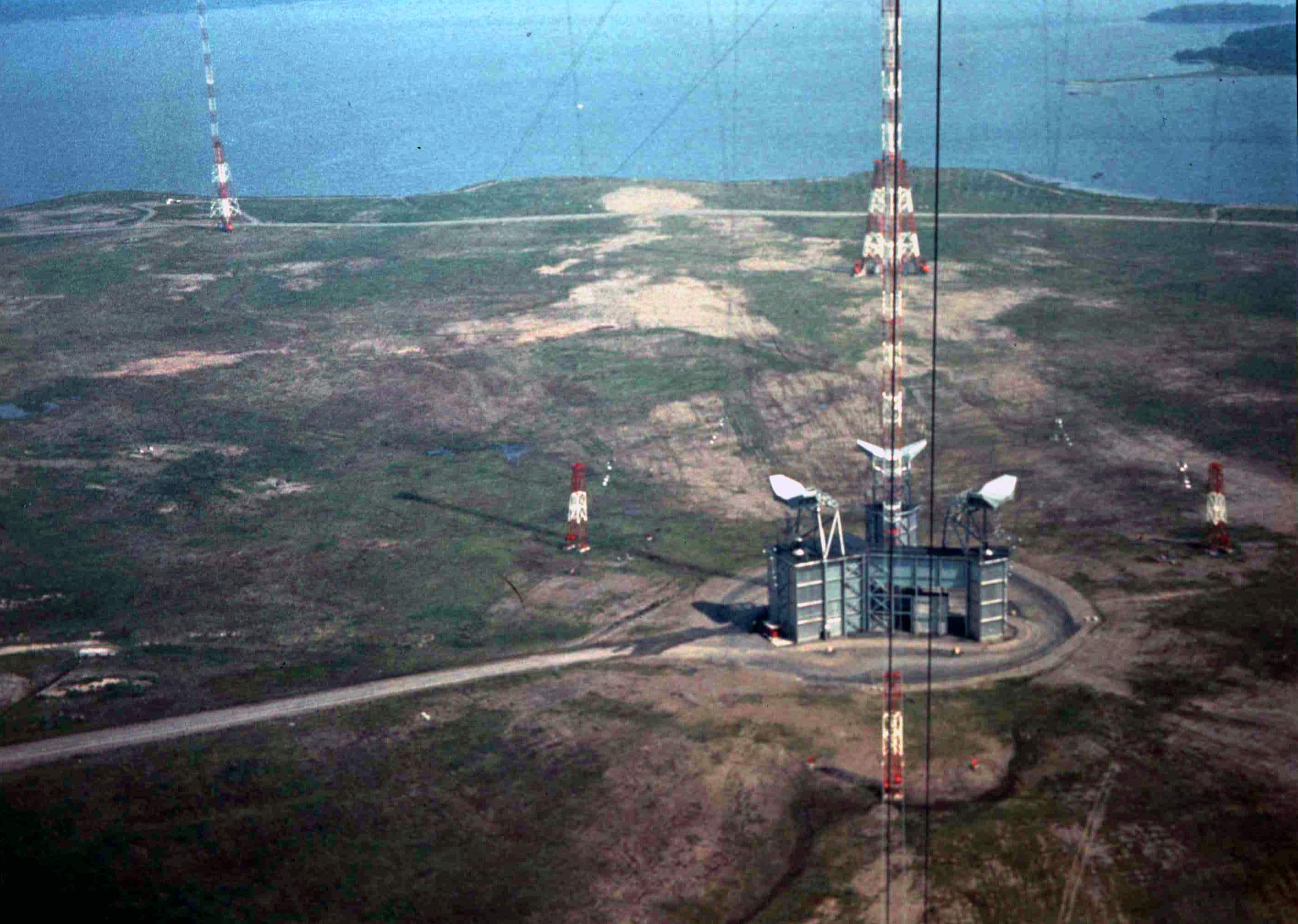
History. The current Cutler station was built from 1958 (the project started 13 January 1958 according to All Hands) and went on the air on 4 January 1961, a full year ahead of schedule. [DOCUMENTED] The call sign NAA was carried over from the old Navy station at Arlington, Virginia, which had used it since 1912 or 1913. [DOCUMENTED, All Hands 1961; the old article gave 1913, and sources differ on the exact start date] It served as the Atlantic VLF broadcast station in support of the Polaris fleet ballistic missile submarine programme, whose first patrol began in late 1960. The BuShips Journal in 1960 says that the station's "usefulness in the Polaris missile system changed the urgency and resulted in an acceleration of funding". [DOCUMENTED] The prime contractor was Continental Electronics of Dallas, Texas, which designed and built the antenna, ground system, power plant and transmitter under contract NObsr 71360 and later NObsr 75244. The contractor accepted a $500,000 warranty for the 1 MW radiated-power requirement. [DOCUMENTED]
Site. About 3,000 acres on the peninsula between Little Machias Bay and the Atlantic near Cutler, Maine, of which about 2,850 acres hold the VLF antenna. The station force was planned at about 160 people with a self-contained village of 50 to 60 acres, 12 miles of road and a fuel pier on Machias Bay. [DOCUMENTED] During construction there were more than 1,500 workers, and the contractor's own brochure says the job needed about 100,000 cubic yards of rock excavation, 2.5 million cubic yards of earth, 12,000 tons of steel for towers, 50,000 cubic yards of concrete (All Hands says 35,000; sources differ), and 3,000 tons of bridge-strand cable for guys and halyards. [DOCUMENTED]
Frequency. The station now uses 24.0 kHz. It used 17.8 kHz in the past according to one published listing, and the Navy page for the site describes a tunable range of roughly 14 to 24 kHz. [SINGLE-SOURCE for 17.8; DOCUMENTED for 24.0] The 1959 specification, as recorded in the old page, called for tunability across about 14 to 30 kHz. [UNVERIFIED] The Navy's 1997 report states that one array (six panels) can radiate full power at 24.0 kHz without help from the reactor, but at lower frequencies the Q is higher and the reactor is needed. [DOCUMENTED]
Power. The original contract called for a transmitter with a nominal output of 2 MW and an expected radiated power of 1 MW. [DOCUMENTED] The Navy's 1997 report describes the present operation: "this site normally operates with a radiated power level of 1-million watts, termed 'full power', and at times as high as 1.8-million watts radiated, termed 'maximum power'". [DOCUMENTED] Public listings differ. Wikipedia gives 1.8 MW as input power, and a 2 MW transmission power in the text; a Stanford amateur VLF station list gives 1,000 kW radiated. [Sources differ. This page uses the Navy statement, and treats 1.0 MW as the normal radiated power and 1.8 MW as the maximum radiated power.]
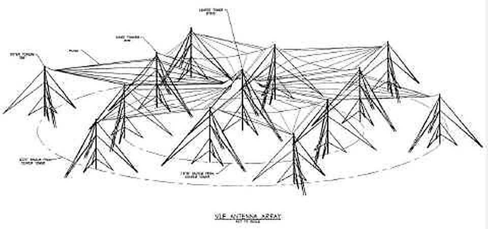
The antenna: two Trideco arrays. The antenna is two identical arrays, north and south, called Trideco arrays, each with thirteen towers. The two central towers are over a mile apart. [DOCUMENTED, All Hands 1961] In each array:
(The 1994 Navy summary prints the middle-tower height as 575 ft, which is a typographical error given the other sources, all of which say 875 ft.) [DOCUMENTED; discrepancy noted]
Each array carries six diamond-shaped top-load panels, hanging from the towers on halyards. A panel is supported from four towers: the central one, two of the inner ring and one of the outer ring. From above, each array looks like a six-pointed star or snowflake, with a diameter of about 6,140 ft (1.87 km). Each panel consists of eight active RF conductors, which carry the radio current, and one support catenary cable that crosses them at the centre of the diamond. [DOCUMENTED] The Navy report says the cables are mostly one-inch Calsun bronze strand, with some sections 1.5 inches in diameter, hollow-core cables made of copper tubes inside Everdure alloy wires. [DOCUMENTED] The QST article of October 1961 gives the total as some 62 miles of one-inch copper cable. [DOCUMENTED, with the note that the later Navy report says bronze, not copper, for the conductors. Different parts of the system may use different cables.]
The radiating section is the set of vertical wires around the central tower, which carry the antenna current from the helix house up to the panels. The horizontal panels are the top-hat. The principle is the one described above: a very large capacitor on top of a vertical radiator, with the ground system as the other plate.
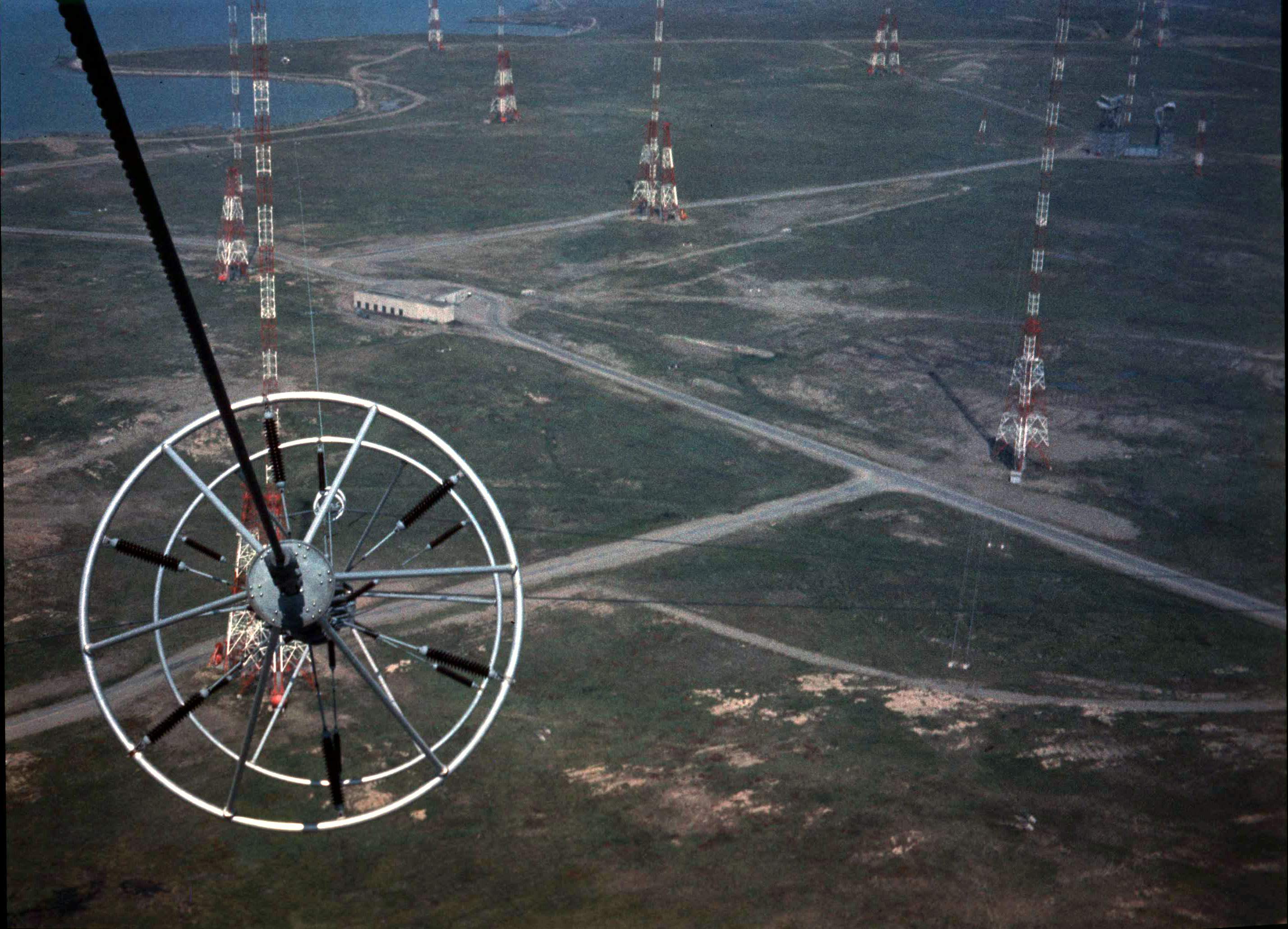
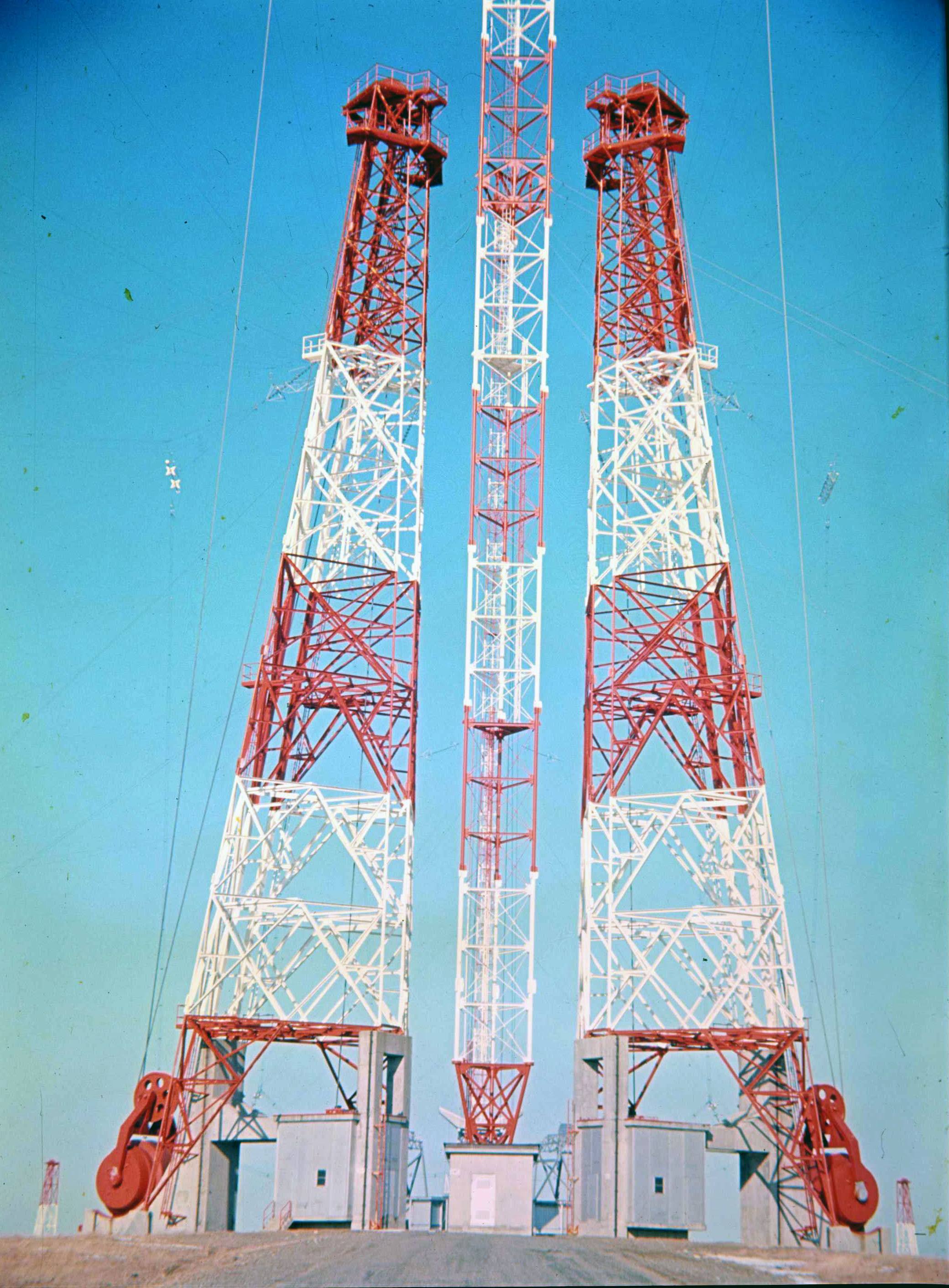
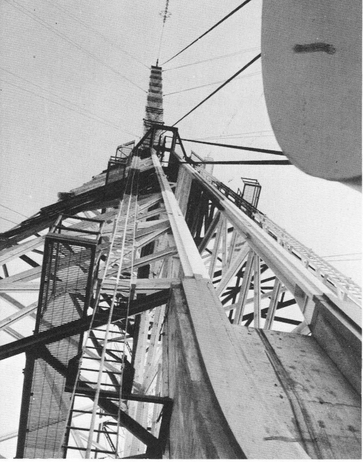
Insulators. The halyards that hold each panel are insulated from the panel by strings of 16 Lapp compression-cone fail-safe porcelain insulators with large grading rings at each end. One insulator weighs about 750 lb, and one string with its hardware weighs over six tons. There is one string at each panel corner, so each panel carries more than 24 tons of insulators. [DOCUMENTED, Navy 1994 summary] A string has to be an insulator for hundreds of kilovolts of radio-frequency voltage, support tons of tension, and survive ice and salt fog.
The counterweight system. Each panel is held up by halyards led to counterweights that roll on stub towers beside the main towers. As ice builds, the added load lets the counterweights pull the halyards out and lower the panel. In principle the panel can come all the way to the ground without breaking anything. As the ice melts, the counterweights hoist the panel back. The maximum design tension in each halyard at peak wind was 110,000 lb, and electric hoists at each tower let each panel be raised and lowered for maintenance. [DOCUMENTED] During installation the panels actually lowered all the way to the ground at least once. [DOCUMENTED, Navy 1994]
De-icing. Lowering the panel solves the mechanical problem but creates an electrical one. As the panel sags, its capacitance to ground rises and the antenna detunes. The tuning range is finite, and when it runs out, transmission stops. The answer is to melt the ice by passing 60 Hz current through the wires, using the fact that the conductors are made of a deliberately resistive alloy, Calsun bronze (19 percent as conductive as copper), whose resistance is low enough for acceptable RF loss and high enough for effective heating. The design heating value was 1.64 watts per square inch of cable surface, approximately 500 kW per panel, about 3 MW for one array, and the system can run at up to four times that. [DOCUMENTED, Navy 1994 and Wikipedia] The previous version of this page said about 7.5 MW; that number is not supported by the Navy's report and has been replaced. The Navy's own report adds the remark that "deicing power significantly exceeds transmit power."
Building a de-icing system that works during transmission would have been prohibitively expensive, because the 60 Hz heating current and the RF would share the same wires. So the answer was two arrays. One transmits while the other de-ices, and ice is allowed to build up on the transmitting array as long as the other array can be cleared before the transmitting array reaches the limit of its tuning range. Then they swap roles. The same two-array design allows maintenance: one array can be grounded and worked on while the other radiates. Antenna maintenance is done in summer. The region where the two arrays approach each other near the transmitter building is called the bow-tie area, and radiation-hazard rules forbid work on the towers there while either array is transmitting. [DOCUMENTED]
One former station maintenance chief (Bob Mhoon, quoted on the navy-radio.com Cutler page) says that if de-icing failed, the arrays would settle down on the counterweights and "you had to deice manually with baseball bats". [SINGLE-SOURCE, anecdotal]
The helix house. At the base of each central tower there is a building called the helix house. The original BuShips description says it contains the antenna tuning and coupling components and the de-icing switchgear. [DOCUMENTED] The Navy's 1997 report describes the components: [DOCUMENTED]
The transmitter is in a separate building about halfway between the two arrays. The 100-ohm transmission line and the control and monitoring cables run to each helix house through a tunnel big enough to walk through. [DOCUMENTED] QST in 1961 published a photograph of the station's chief technician standing inside the copper-lined concrete tunnel where the coaxial matching section runs. [DOCUMENTED] The old version of this page described the line as large enough for a man to stand in, which agrees.
Former maintenance chief Mhoon describes the helix house as a four-storey building. He remembers a "massive insulator on top ... that looks like a spark plug", sealed and filled with inert gas, that "generally failed in the winter and was hell to change". [SINGLE-SOURCE]
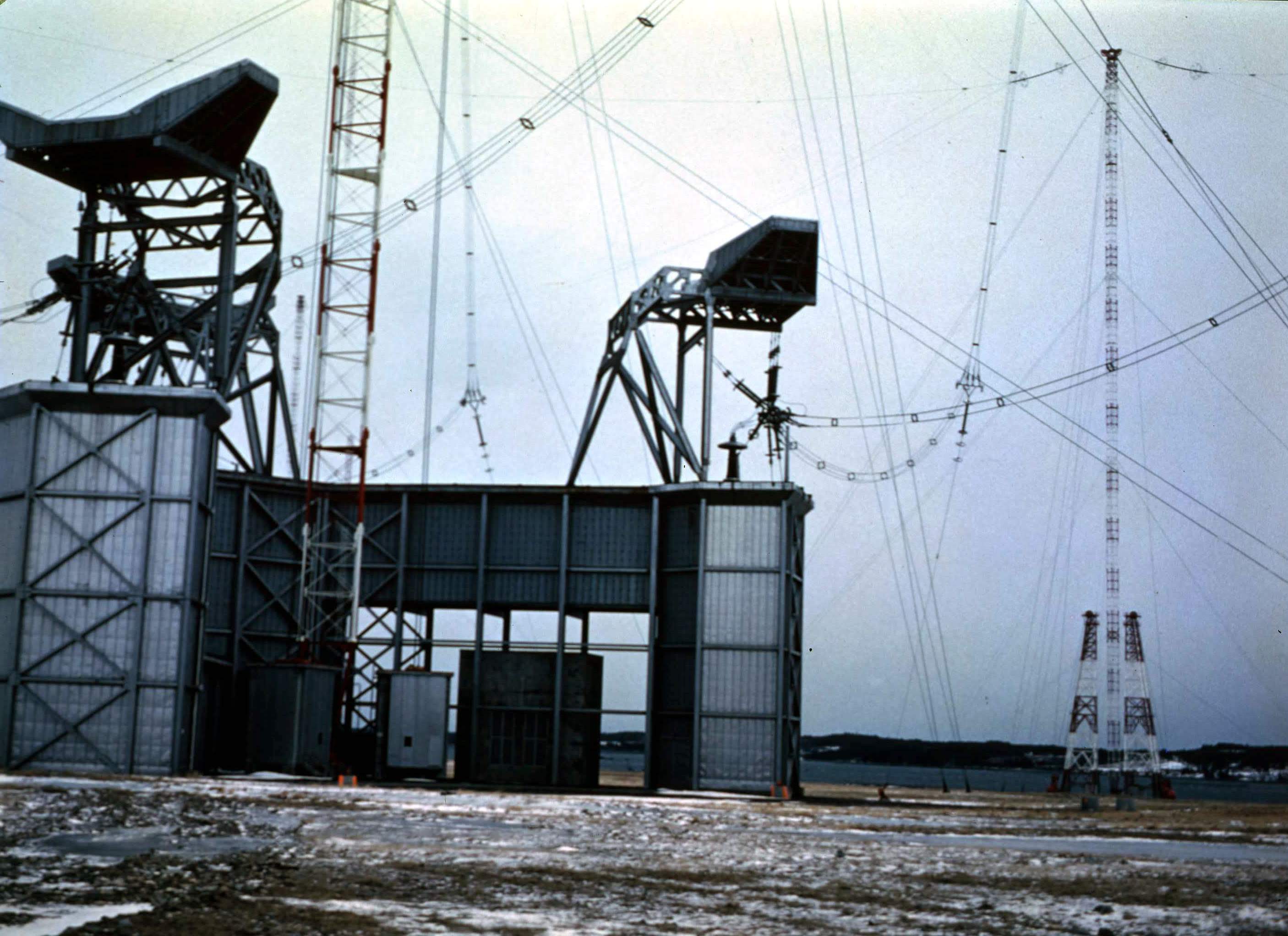
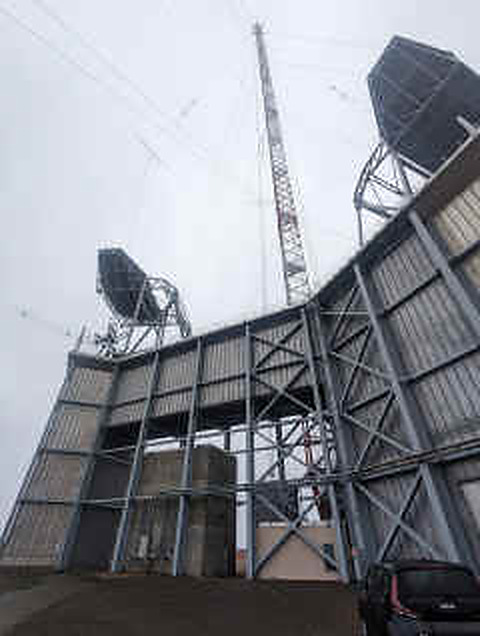
MSK and the saturable reactor. The Navy report explains a particular trick. MSK uses two frequencies, a mark and a space, and a high-Q antenna cannot follow a rapid change between them. Without help, the antenna would resonate at only one of them. The saturable reactor receives an "antenna tune" signal from the modulator and retunes the antenna in step with the mark and space frequencies, so that the antenna is resonant at whichever frequency is being sent and the transmitter always sees a nearly resistive load. The Navy's phrase for this is "bandwidth enhancement". [DOCUMENTED] It is a good example of how the design is limited by Q: the antenna is so efficient and so narrow that the keying has to be matched to it.
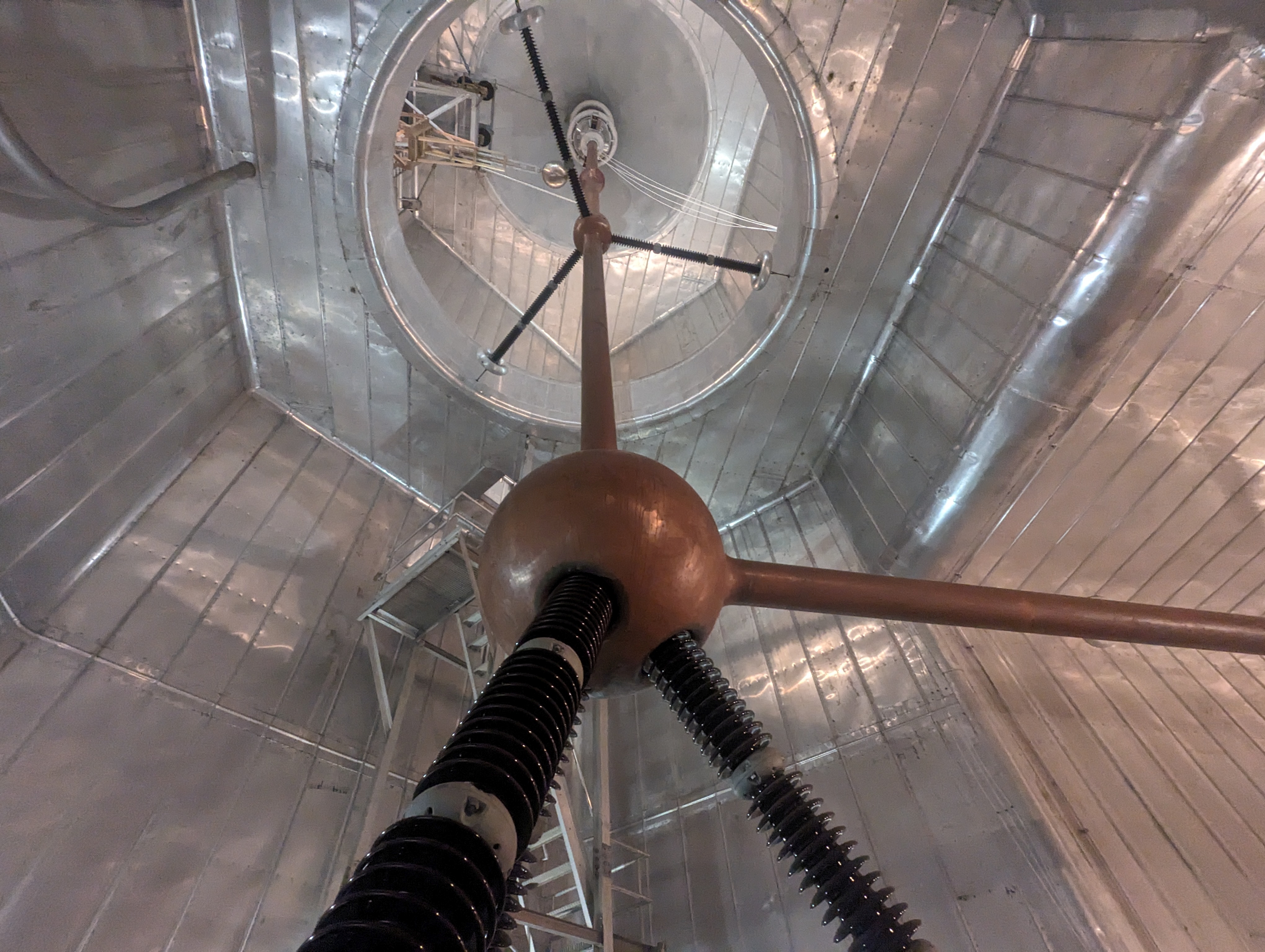
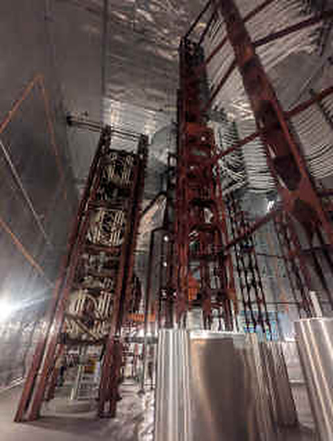
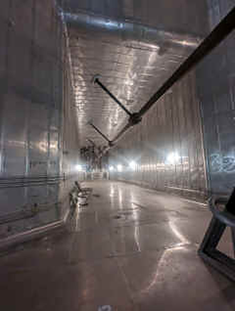
The ground system. The copper ground net, with more than 2,000 miles of No. 6 wire (about 1,000,000 lb, buried 12 inches deep) fans out from each array to the sea. The wires collect the radio-frequency displacement currents and return them to the helix houses with low loss. [DOCUMENTED]
Power plant. Cutler is far from the grid for its needs, and the Navy built its own diesel plant. The 1960 plan was for generators of 11,000 kW for the transmitter, station lighting, hoists, tower lights and the de-icing circuits. [DOCUMENTED] All Hands in 1961 says the plant could produce "in excess of 15 million watts", about 15,000 kW, and the old page gave 11 to 18 MW. [Sources differ; the plant was probably enlarged. An 18 MW figure also appears in the navy-radio.com site material.] The station burns about 3,000,000 gallons of fuel a year (1961 figure) and receives it over its own pier into a tank farm. Mhoon remembers five very large diesel engines and a storage of 22,000 barrels. [DOCUMENTED for the 1961 numbers, SINGLE-SOURCE for the recollection] A station with its own generating plant and fuel supply can keep transmitting and de-icing for as long as the fuel lasts, which is one of the survivability features covered later.
The transmitter. The 1960 transmitter was four final amplifier units of 500 kW each, combined for full output. Any combination of the four units and the two halves of the antenna could be used. [DOCUMENTED] QST (October 1961) says that each final used eight ML-6697 air-cooled tubes in push-pull parallel. [DOCUMENTED] The transmitter designation is AN/FRT-31 (with AN/FRT-64 and -67 listed in the site's later equipment). In 2000 the transmitters were upgraded with a digital sine-wave-synthesis, solid-state intermediate power amplifier driving the tube final stages. [DOCUMENTED, navy-radio.com summarising Navy documents] The 1990s Navy plan describes the vacuum-tube amplifiers at the fixed VLF sites as "inefficient and unsupportable" and proposed replacing them with solid-state amplifiers (the SSPAR programme) and, in the interim, a service-life extension that was completed at Jim Creek, Lualualei, Cutler and Aguada. [DOCUMENTED] Photographs from 2024 on the navy-radio.com page show ML-6697A tubes still in use, which suggests that at least part of the tube plant remained in service. [SINGLE-SOURCE; what the plant looks like today is not public]
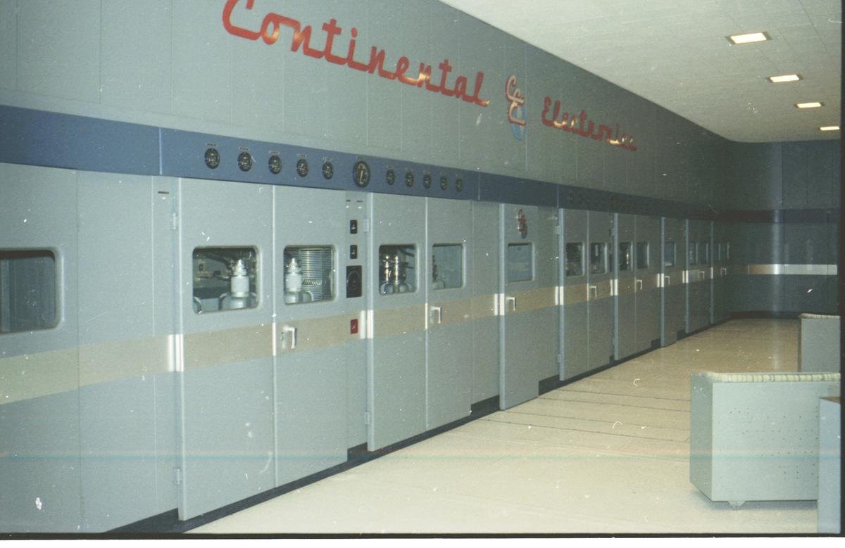
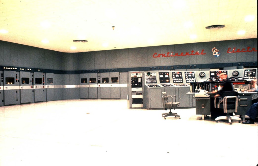
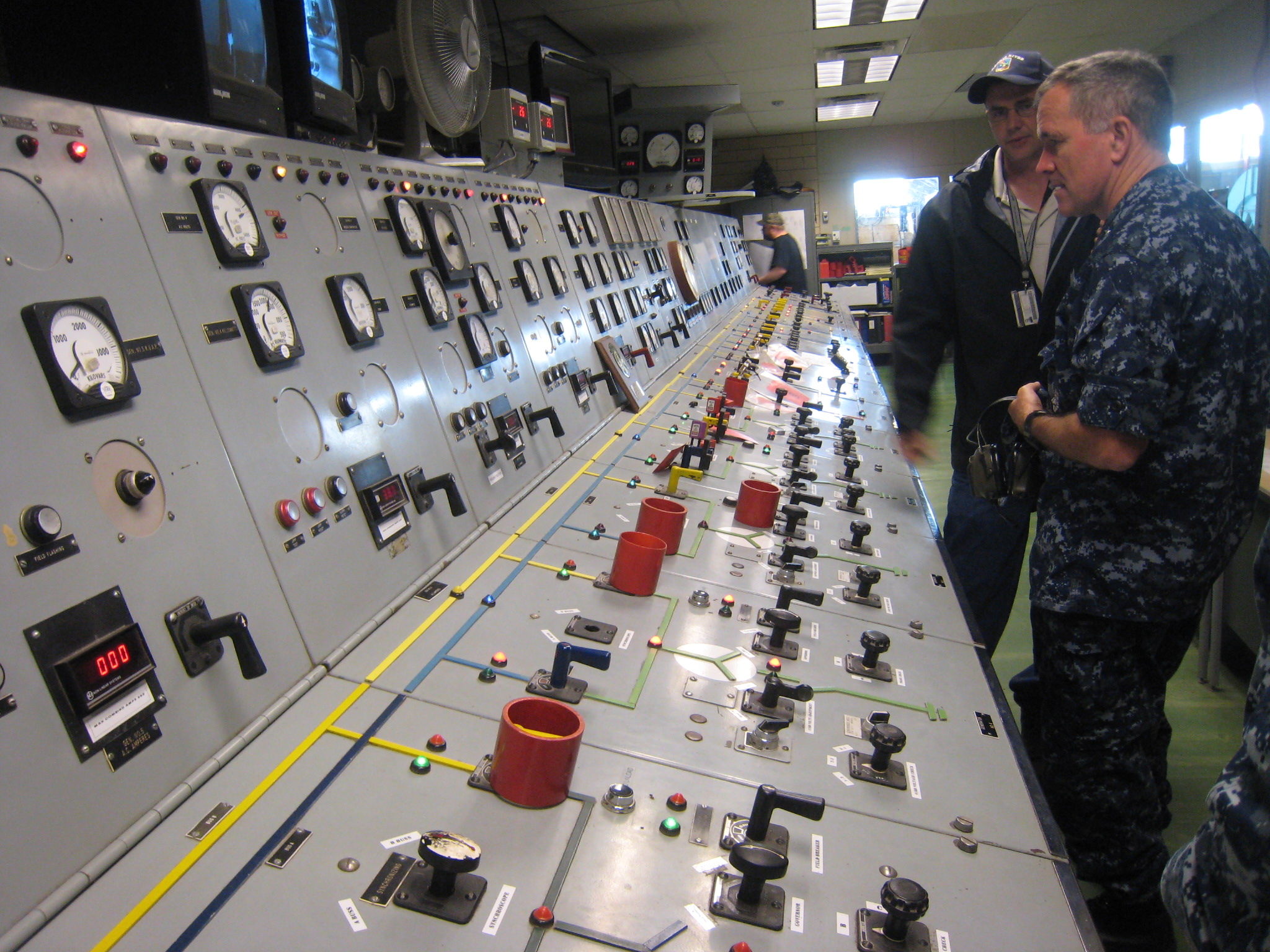
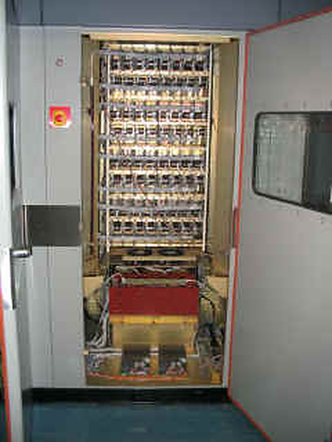
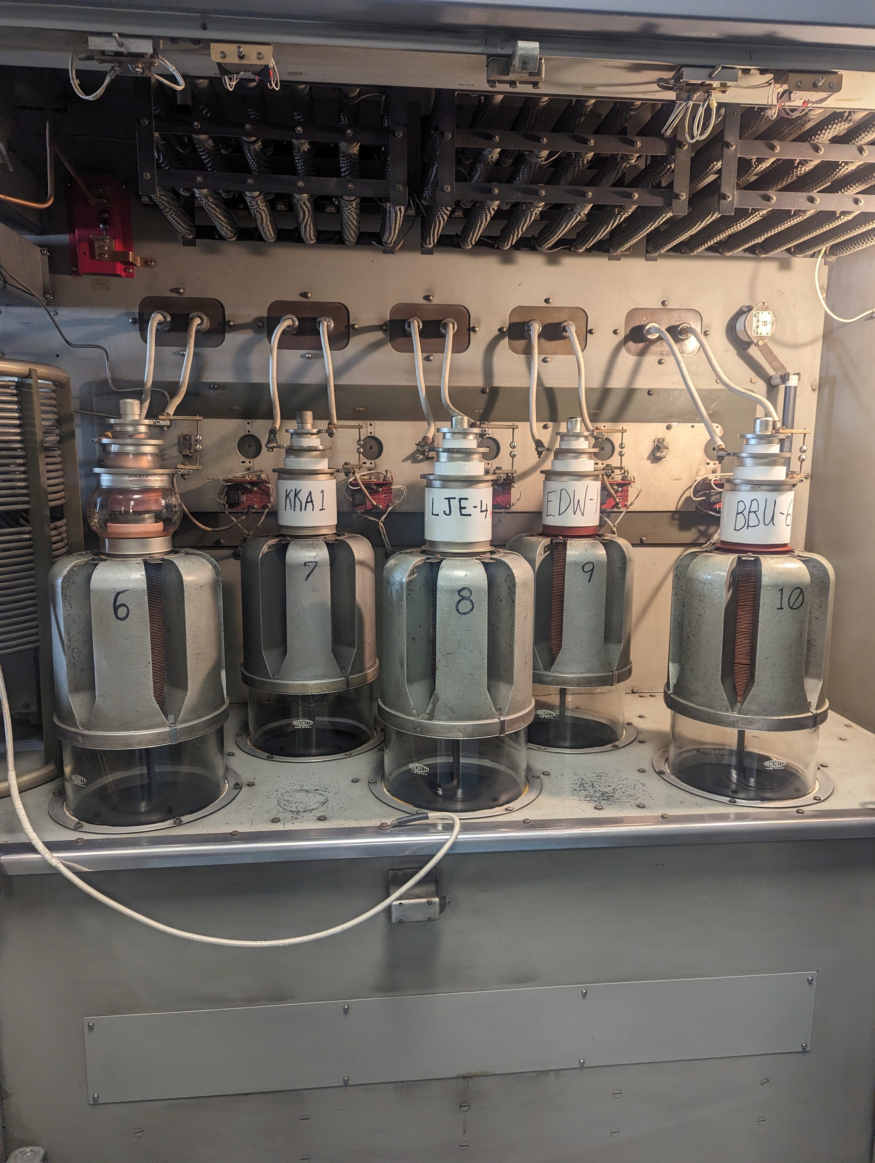
Operations. The transmitter building has about 25,000 square feet of floor space and sits between the two arrays. The cooling system filled the area behind the amplifier cabinets with large fans drawing air from outside through filters. [DOCUMENTED for floor space, SINGLE-SOURCE for the fan description] Mhoon's account also includes a combiner room where the coax meets the transmitter, with copper-plated walls and banks of capacitors; he says visitors on tours were asked to hold fluorescent tubes which lit up from stray RF when raised overhead. [SINGLE-SOURCE, anecdotal] It is a nice illustration of the strength of the near field around a megawatt transmitter.
Modulation at Cutler. In 1961 the transmitter could send 25 words per minute of on-off keying and 60 words per minute of frequency-shift keying. [DOCUMENTED, All Hands 1961] Modern operation uses minimum-shift keying, multi-channel and encrypted. A 200 baud figure has been published for the station's emission, which matches the four-channel 50 baud format described in the signal section. [DOCUMENTED for the format in general; the figure for Cutler specifically is from published frequency lists and I treat it as SINGLE-SOURCE]
JIM CREEK (NLK) IN DETAIL
History. Planning started at the end of the Second World War. In March 1946 the Chief of Naval Operations told the Bureau of Ships that the Navy needed modern high-power VLF facilities, particularly for the far western and northern Pacific, and in August 1946 field surveys began for a site in the Puget Sound area. The requirement was a mountain-span catenary antenna strung between two peaks of about equal height, with the valley floor at least 2,000 feet below, plus a large power supply nearby and ground conductivity close to ideal. The Jim Creek valley was recommended in 1947, construction began in spring 1949, and the station went into operation on 18 November 1953. [DOCUMENTED, BuShips Journal March 1954 as reproduced on navy-radio.com] The transmitter was designed and built by RCA. Life magazine described it as a $14 million installation that took six years, and said the first message was dictated by Admiral Robert Carney and sent in code by RCA's David Sarnoff, after which acknowledgements came back within minutes from a battleship off Japan, a carrier in the western Pacific and a submarine far off in the Atlantic. [DOCUMENTED, Life 1953 as reproduced on navy-radio.com]
Site. The valley lies in the Cascade foothills north-east of Seattle, near Oso, Washington. The 1954 description gives 725 acres for the original reservation. Current descriptions give about 5,000 acres (the larger figure includes the surrounding forest and recreation land) and a 2017 Navy statement quoted by the Seattle Times gives 980 acres for the antenna network. [Sources differ because they measure different things]. The Navy cleared about 2,000 acres of heavily wooded slopes and spent nearly a year cutting Douglas firs from the valley slopes, partly to remove fire risk and partly because, in the words of the 1954 article, "trees tend to absorb large quantities of the energy radiated by the antenna". [DOCUMENTED] The ground net is over 200 miles of copper. [DOCUMENTED]
The antenna: a valley-span. The antenna is quite different from Cutler's. It is a capacitively top-loaded short monopole in which the mountains do the work of the towers. [DOCUMENTED]
A 2012 Navy "Antenna Replacement Project" lowered and replaced spans and insulators, and contractors in the Navy photographs work on antenna wires lowered to the ground. A later Seattle Times article quotes a 2017 Navy statement of "six 200-foot-tall towers" and "more than 360 miles of copper cable conductors" forming the antenna. [DOCUMENTED, but the two descriptions of the tower count disagree with the 1954 article and other descriptions; this page uses 12 main towers plus 23 bus towers]
Effective height, efficiency and radiated power. The old version of this page gave an effective height of about 110 m, an efficiency near 20 percent at 24.8 kHz, a bandwidth near 50 Hz, and a radiated power on the order of 200 to 250 kW from a transmitter of about 1.0 to 1.2 MW. [UNVERIFIED as to the first three] The independent confirmations are these. Wikipedia and Navy material give a transmitter power of 1.2 MW, Life gave 1.2 MW in 1953 while BuShips gave 1,000,000 W "conservatively rated". The Stanford SID station list gives a radiated power of 250 kW, which implies about 21 percent efficiency for a 1.2 MW transmitter. [DOCUMENTED for the 1.0 to 1.2 MW transmitter rating; SINGLE-SOURCE for the 250 kW radiated figure] Physically, a lower efficiency than Cutler is what one would expect from a smaller effective height (R_rad of about 0.12 ohm against 0.36 ohm) with a comparable loss resistance. [ESTIMATE]
The building. The transmitter building is a windowless concrete structure several storeys high, with a foundation 35 feet below the surface, stabilised against earthquakes and lined throughout with copper sheet to shield its contents from the intense field. The transmitter is on the second floor, and the ground floor holds power transformers, switchgear, pumps, distilled-water tanks and heat exchangers. At the rear of the building are two integral helix houses, each 75 feet square and 60 feet high, housing the loading coils and variometers. A lead-in "barrel", 86 feet long, carries the antenna feed from the helix room outward; visitors during construction thought it was "an atomic gun". [DOCUMENTED]
Transmitter. The RCA transmitter was a pair of 500 kW transmitters (AN/FRT-3) in a U-shaped arrangement with the operator's console in the middle. Each power amplifier uses two (with a third as a spare) 500 kW high-vacuum triodes in push-pull. The tubes are about 10 inches in diameter, about 39 inches long and weigh 135 lb, with water-cooled anode, grid supports and cathode beam former, a thoriated-tungsten filament drawing about 13 kW, plate voltage 11.5 kV and 80 percent plate efficiency. [DOCUMENTED] The transmitter begins with a crystal-controlled variable oscillator tunable over 14.5 to 35 kHz with a stability of 0.001 percent and about 1 watt of output, multiplying up by about sixty dB to 1 MW. [DOCUMENTED] It had microsecond fault protection, which relieves a tube arc in a few millionths of a second before the fault current can build up and wreck the tube. [DOCUMENTED] Power came from the Bonneville Dam transmission line via a site substation at 4,160 V three-phase, about 2,000 kW being needed for the transmitter and other facilities, with a diesel plant planned for emergency power. [DOCUMENTED]
The old version of this page called the later finals "5831 class" triodes; no source for that designation was found, so it is [UNVERIFIED].
Keying and control. The 1995 Navy facility report says the primary and secondary transmitter keying circuits came from NAVCOMMSTA Stockton via leased telephone lines and/or a UHF microwave circuit, with computerised order-wire circuits to NAVCOMTELSTA Puget Sound and the NAVCOMM Detachment at Whidbey Island. [DOCUMENTED] That means the station is keyed remotely from other facilities rather than carrying its own message-generation staff, consistent with the Navy's plans to consolidate broadcast keying stations.
Callsign. The call sign is NLK. The old page said earlier listings also show NPG for the site. [UNVERIFIED, not re-checked]
POWER: THREE DIFFERENT NUMBERS
The numbers quoted for a VLF station often look inconsistent because they describe different things. Three must be kept apart.
For Cutler: nominal transmitter output 2 MW, radiated 1 MW normal, up to 1.8 MW maximum (Navy). The design assumed 50 percent efficiency. Where one source says "up to 1.8 MW input", it appears to be the same 1.8 MW maximum figure with a different label. For Jim Creek: transmitter output 1.0 to 1.2 MW, radiated about 250 kW (single source), efficiency about 20 percent. [DOCUMENTED / SINGLE-SOURCE as above]
Why is the megawatt even needed? Because the signal must beat atmospheric noise at the far end of the path in the narrow bandwidth of the slow data signal, and because the penetration into the sea costs 50 to 100 dB. Doubling the radiated power adds only 3 dB. The Navy found it more effective to use signal processing than more power, as the "Range Extension Mode" in the 1990s plan shows (less transmitter power is required "because it takes advantage of signal encoding and compression techniques"). [DOCUMENTED]
Power efficiency also matters in the electrical bill: a 2 MW input for a transmitter with 60 percent AC-to-RF efficiency means a power demand of well over 3 MW from the grid or generators, plus the de-icing demand of about 3 MW, plus the station. Continental Electronics later developed VLF transmitters in which the reactive power is returned to the DC supplies, raising the AC-to-RF efficiency from about 60 percent (large tube plants) toward about 80 percent. [UNVERIFIED, carried forward from the old version of this page; the original source was not found]
HOW THE SIGNAL IS BUILT: MSK, 50 BAUD, FOUR CHANNELS
One-way, narrow-band, slow. The physical bandwidth of the system is set by the antenna Q: roughly 50 to 200 Hz depending on the station. Information rate is limited by bandwidth (in the Shannon-Hartley sense, capacity C = B log2(1 + S/N)), and the signal-to-noise ratio in a lightning-noise-limited VLF channel is modest. Navy VLF broadcast speeds are therefore tens of bits per second per channel. [DOCUMENTED]
The modulation: minimum-shift keying. The 1960s signal was on-off keyed (25 wpm) or frequency-shift keyed (60 wpm). Today it is minimum-shift keying (MSK), a form of continuous-phase frequency-shift keying in which the two tones are spaced by exactly half the bit rate (the minimum spacing at which they are orthogonal over one bit period). For an MSK stream of R bits per second the mark and space frequencies differ by R / 2. At 50 bit/s that is 25 Hz, and for a four-channel 200 bit/s stream, 100 Hz. [ESTIMATE, from the MSK definition] MSK has two properties that suit a VLF station. The envelope is constant, so the power amplifier works at constant power and the stress on the supply does not fluctuate, which the Space Academy page says is "less strain on the power system" than on-off keying, which is "particularly bad". And it has a compact spectrum, with low side lobes, so more of the power stays within the antenna's narrow resonance.
Channels. The 1990s Navy description says VERDIN "multiplex[es], encrypt[s], encode[s], and modulate[s] up to four 50 bps submarine broadcast channels". NATO's STANAG 5030 standard defines modes: N1 is a single-channel on-off-keyed Morse mode, N2 a single-channel 50 baud FSK mode, N3 a two-channel 100 baud time-division multiplexed MSK mode, N4 a four-channel 200 baud TDM MSK mode with 50 baud per channel, and N5 also four channels at 200 baud in which, for US transmitters, three channels belong to the US as nationally controlled and formatted channels, and N6 a two-channel 100 baud mode. [DOCUMENTED, via a published summary of the standard] The same document states that the US modified the shipboard VERDIN receivers, and one channel at Cutler and Aguada, to be STANAG 5030 MSK capable, to be interoperable with NATO. [DOCUMENTED] That means that at least one channel of the Cutler broadcast follows an international standard and the others are national.
Dynamic channelization and range extension. The same plan describes the idea of reconfiguring a four-channel broadcast to two or one channel, which gives more energy per bit and so the same message at lower transmitter power or longer range; "split array" operation to send two separate broadcasts on different VLF frequencies; and range-extension coding. [DOCUMENTED as plans in the 1990s, current status not public]
Encryption and the broadcast schedule. The broadcast is encrypted, and the content is a "continuous transmission sequence of prioritized messages which normally lasts two hours". [DOCUMENTED] Every submarine on patrol that can hear the broadcast decodes the channel and picks out messages addressed to it (or all boats), without any transmission of its own. This is the essential property of a broadcast system: the shore has no idea which submarines are listening, and an enemy cannot learn anything about the boats by listening to the shore.
Why only text. At 50 bit/s with, say, five bits per character, the channel carries about ten characters a second, far more than ELF but nothing like voice (which needs at least a few kilobits per second even when heavily compressed). A short formatted order of tens of characters takes seconds. The channel is used for short coded messages, routine fleet traffic and the scheduled broadcast. Details of what the messages contain, including the format of any strategic order, are classified and not described here.
THE MESSAGE: EAMS AND THE BROADCAST CONTROL AUTHORITY
The 1990s plan states that JCS and USSTRATCOM can take over the BCAs "at any time, for EAM dissemination". An Emergency Action Message (EAM) is a short, formatted, authenticated message conveying a strategic order. EAMs are sent over several paths, including the Navy's VLF and LF broadcast to submarines, the HF Global Communications System (see HFGCS) to aircraft and other forces, and, for ICBM forces, other dedicated systems. The Strategic Communications Continuing Assessment Program and the Fleet Ballistic Missile Continuing Evaluation Program, run by the Johns Hopkins University Applied Physics Laboratory, assess the delivery of EAMs to SSBNs. [DOCUMENTED, FAS plan] The format and authentication of EAMs are not public, and this page does not describe them. How these messages are generated at the top of the chain is covered in the article on Cheyenne Mountain and its role in command and control, and the Russian equivalent in the article on Perimeter.
HOW A SUBMARINE RECEIVES VLF
Receive antennas. A submarine cannot raise a mast and receive VLF underwater. The options are:
Effective height. The voltage that an antenna delivers is V = E x h_eff, where E is the incident electric field and h_eff the effective height. With a field of about 1 mV/m (typical of the signals in the estimates above) and h_eff of 20 mm, the open-circuit voltage is about 20 microvolts. [ESTIMATE] That is workable for a good receiver, because the bandwidth is tiny. The patent describes a spot measurement using Cutler (NAA, 24.0 kHz) as a beacon, in which an inexpensive loop received -90.5 dBm and the patented antenna received -57.5 dBm. The ratio is 33 dB, which corresponds well with the ratio of effective heights quoted, 31 mm against 0.79 mm (a factor of 39, 32 dB). [DOCUMENTED: figures from the patent text; the arithmetic confirms they are consistent]
Depth. The boat does not need the antenna deep. The buoyant cable lets the boat itself stay at depth while the antenna section floats near the surface, although how deep depends on the cable length and the boat's speed, and these are classified. A submarine copying a VLF broadcast has to slow down, because the cable tension and the antenna's shape depend on speed; Navy statements describe the ability to "remain at required mission depth and speed" as a benefit of ELF, which implies that VLF imposes constraints. [DOCUMENTED for the benefit of ELF; the inference about VLF constraints is the author's, UNVERIFIED]
The receiver. The receiver is an AN/WRR-7 in the 1960s-1990s VERDIN system (R-1738/URR receiver, MD-855/WRR-7 demodulator, CP-1071/WR processor, O-1612/URC frequency standard). Modern submarine VLF receivers are software-defined and DSP-based, typically covering about 15 to 25 kHz. [DOCUMENTED for the legacy equipment, SINGLE-SOURCE for the modern description] The receiver must recover the MSK, hold the bit clock (the frequency standard helps), de-interleave, error-correct, decrypt and print or display the message.
Replies. The boat does not reply on VLF; a submarine could not, with a transmitter of a size that fits in a boat, radiate at 24 kHz with useful power. A reply needs the boat to raise an antenna and use HF, UHF satellite or other paths, and it is done when the boat's captain judges it safe. The Navy uses the Submarine Satellite Information Exchange System (SSIXS), a UHF satellite link at 4,800 baud in the 1990s, and the Officer in Tactical Command Information Exchange System (OTCIXS) at 2,400 baud, and HF circuits such as Mayflower and Clarinet Merlin. [DOCUMENTED, FAS plan] Newer high-data-rate paths use EHF and commercial satellite resources. [DOCUMENTED as plans]
TACAMO: THE AIRBORNE BACKUP
The shore stations are fixed targets whose positions are known to everyone. The Navy's answer to that is an aeroplane.
History. The TACAMO ("Take Charge and Move Out") mission began in 1961 as a test, using a US Marine Corps KC-130 to find out whether an airborne VLF system was feasible. The test was a success. In early 1963 four C-130 aircraft were taken from the production line and modified as C-130Gs, the first delivered on 26 December 1963, with the radio equipment in removable vans. In 1966 a plan was made to install the equipment permanently in eight aircraft as EC-130Qs, VQ-4 was established at NAS Patuxent River on 1 July 1968, and in 1974 a new power amplifier, a dual trailing-wire antenna and a high-speed reel system for deploying and retracting the wires were fitted. The aircraft was replaced by the Boeing E-6A Mercury (a 707 derivative), whose first delivery to VQ-4 was in 1991 (the Navy accepted the first in August 1989, and the first production aircraft flew in 1987). The E-6B added the Looking Glass airborne command post mission and the Airborne Launch Control System for ICBMs, accepted from December 1997. [DOCUMENTED, VQ-4 history as reproduced on navy-radio.com, key.aero and NAVAIR]
The system. The E-6B carries a VLF transmitter rated at 200 kW. The designation of the E-6B transmitter set is given as AN/ART-54 high power transmit system (HPTS) with a dual trailing-wire antenna OE-456, made by Rockwell Collins; the earlier tube transmitter was OG-193 in the USC-13 system. [DOCUMENTED] The antennas are two retractable wires, a long one reported as 28,000 ft (8.5 km) and a shorter one of 5,000 ft (1.5 km). [DOCUMENTED, key.aero; the navy-radio page for the EC-130 era gives about 25,000 ft, and an aerospace magazine says 2.5 miles, so the length depends on the aircraft and the date. Sources differ]
Flying the antenna. The antenna has to stand up almost vertically to be a vertical monopole. Once the wire is deployed, the induced drag slows the aircraft to about 10 knots above stall speed, and the aircraft flies a tight orbit (a bank of 25 to 40 degrees), so that the wire hangs nearly vertical below it like a plumb line. [DOCUMENTED, key.aero] The wire, the aircraft and the hanging weight together make a vertical antenna in the sky, with the sea underneath acting as ground.
Physics. An 8.5 km wire at 24 kHz is about 0.68 of a free-space wavelength, so unlike the shore stations, it is not electrically short. A quarter-wavelength at 24 kHz is 3.1 km. [ESTIMATE; the frequency used is unpublished, and the aircraft may use a different VLF frequency or a different part of the 14-60 kHz range] This is why a 200 kW transmitter in an aircraft can radiate usefully despite the aircraft's tiny size. It has a long wire, but the radiating part is limited by the height above the sea of the aircraft and by how vertical the wire hangs. Its radiated power is not public.
Role. TACAMO "provides survivable VLF/LF MEECN mode, HIDAR, and EHF transmissions during trans-attack and post-attack phases", in the Navy's words from the 1990s plan. [DOCUMENTED] In other words, if the fixed stations are destroyed or cut off, a TACAMO aircraft can relay the order from the airborne command post to the submarines using the same VLF receivers they already have. Two squadrons, VQ-3 and VQ-4, operate from Tinker Air Force Base, Oklahoma, and the Navy lists 16 aircraft. [DOCUMENTED, NAVAIR and the Navy training plan] The E-6B also handles relay to land-based ICBM forces, and carries the equipment to serve as a command post for USSTRATCOM. Replacement plans for the E-6B have been discussed publicly; this page does not cover them. [UNVERIFIED]
Why a trailing wire is much more demanding than it sounds. The wire is weighted, lowered through a reel, and must withstand the same corona problems as a fixed antenna at tens of kilovolts. The aircraft's own generators are sized for the transmitter; the navy-radio page describes the EC-130 as having its four standard generators plus four additional 60/90 kVA units for the nominal 200 kW power amplifier. [SINGLE-SOURCE]
Experimental ideas for other mobile VLF platforms existed. The Navy-radio page lists a transportable system (NOMAD, AN/MRC-99, 100 kW at 15 to 30 kHz, a V-shaped balloon lifting up to 10,000 ft of wire), ship-based concepts with a 10,000 ft antenna lifted by a helicopter, and a proposal for orbiting wires. [SINGLE-SOURCE, historical]
ELF: THE BELL-RINGER
What it was. The Navy's Extremely Low Frequency system used two transmitting sites, one near Clam Lake, Wisconsin, and one near Republic, Michigan, operating at a frequency modulated between 72 and 80 Hz, with the most prominent frequency at 76 Hz. [DOCUMENTED, National Academies review]. A Navy briefing paper from 1984 says the Wisconsin site had 28 miles of overhead antenna line (two 14-mile lines at right angles), operating for more than ten years at that time, and the Michigan site was to have 56 miles. The antennas are long overhead power-line-like wires with buried ground terminals at their ends, in cleared rights of way in forests. [DOCUMENTED] The two sites worked together. The Navy shut the system down on 30 September 2004. [DOCUMENTED] Reported electrical power was in excess of two million watts. [SINGLE-SOURCE, Microwave News]
The physics. At 76 Hz the wavelength in free space is about 3,900 km. A 28-mile (45 km) wire is a hundredth of a wavelength. A horizontal wire radiates poorly, and the way it works is not by radiating from the wire but by driving current into the ground at each end so that a large loop of current flows deep in the earth. The Navy chose the Laurentian shield granite of Wisconsin and Michigan because it is such a poor conductor that the current is forced to flow deep, hundreds of feet or more, and thus electrically lengthens the antenna. [DOCUMENTED, Navy 1984] The signal is guided around the world in the same Earth-ionosphere waveguide, and at ELF the guide is even less lossy, with a few tenths of a dB per Mm. Because of the poor efficiency the radiated power is a tiny fraction of the electrical power. Commonly quoted values are on the order of a few watts. [UNVERIFIED]
The reach. At 76 Hz the skin depth in seawater is about 29 metres and the attenuation about 0.3 dB per metre. [ESTIMATE] A boat at a depth of a few hundred feet can receive it, and the 1990s Navy plan says "several hundred feet below the surface". [DOCUMENTED]
The cost: bandwidth. The data rate was about three characters in five minutes according to the Navy's 1984 paper. [DOCUMENTED] It could not carry a message. It could carry a short code, which was used as a "bell-ringer", an alert telling the boat to come shallow and copy a higher-rate broadcast on VLF or satellite. The 1990s plan says exactly this: the ELF system is used "as a bellringer to notify the submarine crew to come shallow to copy a higher data rate broadcast". [DOCUMENTED] The Navy also demonstrated an "Enhanced Data Rate" mode in 1995, with messages 4 or 13 times longer at somewhat shorter range, but it was not approved for fleet installation. [DOCUMENTED]
Why it was closed. The Navy's stated reasons were not found in the sources used here. The system's cost and the environmental controversies around it were widely reported. [UNVERIFIED as to reasons]
Russia has operated an ELF transmitter called ZEVS at 82 Hz on the Kola Peninsula near Murmansk, with two grounded horizontal antennas about 60 km long, detected by satellites; it is described as one-way. [SINGLE-SOURCE, based on Wikipedia and satellite studies] It is the closest thing in service today to the closed American system.
THE OTHER VLF STATIONS
The Navy's list of fixed VLF sites, as in public frequency tables (with radiated powers from the Stanford SID station list, which has errors and should be taken as a rough guide): [DOCUMENTED for locations and frequencies, SINGLE-SOURCE for powers]
| Station | Call | Frequency | Radiated power (listed) |
|---|---|---|---|
| Cutler, Maine | NAA | 24.0 kHz | 1,000 kW (Navy: up to 1.8 MW) |
| Jim Creek, Washington | NLK | 24.8 kHz | 250 kW |
| Lualualei, Hawaii | NPM | 21.4 kHz | 566 kW |
| LaMoure, North Dakota | NML | 25.2 kHz | 500 kW |
| Aguada, Puerto Rico | NAU | 40.75 kHz | 100 kW (this is LF, not strictly VLF) |
| North West Cape, Western Australia (Harold E. Holt) | NWC | 19.8 kHz | about 1 MW |
Annapolis (NSS) in Maryland, the former Atlantic station, was planned for closure in fiscal 1996, and Cutler took over its role. The 1990s plan says the Navy had six high-powered multi-channel MSK "Fixed VLF" sites and seven multi-channel LF sites worldwide at that time. The North West Cape station, jointly used with Australia, runs 200 baud MSK split into four channels, three used by the US Navy and one by the Royal Australian Navy. [SINGLE-SOURCE, Space Academy]
NATO. NATO has its own submarine broadcast system with transmitters in the United Kingdom (Anthorn), Italy (Tavolara) and Germany (Rhauderfehn), operating in STANAG 5030 modes. National systems exist in France (Sainte-Assise) and, historically, the UK (Rugby and Criggion) and Annapolis. [SINGLE-SOURCE, a published summary of NATO communications] Continental Electronics built NATO VLF stations in England and the Mediterranean in the early 1960s; the Mediterranean one is described in the manufacturer's brochure as installed in a gallery deep in solid rock with blast-closure devices, emergency power and decontamination for the operating staff, with an emergency antenna conceived on the premise that the main antenna would be swept away. [DOCUMENTED as a contractor's description; the station is not named in the brochure and this page does not guess] It is the clearest published example of an attempt to harden a VLF station, and it shows that the designers considered the problem.
Russia and the Soviet Union. The Soviet and Russian Navy have also used VLF and ELF systems for submarine communication, including the ZEVS ELF station mentioned above. The Alpha (RSDN-20) VLF system is a navigation system, not a command broadcast, the Soviet counterpart of the Omega system; its transmitters are in the Novosibirsk, Krasnodar and Khabarovsk regions. [SINGLE-SOURCE] This page does not cover Russian submarine communications in detail. The Russian command chain is described in Russian C3, NDMC and, for the last-resort system, Perimeter and Object 1335 (Grot).
China. Wikipedia's Jim Creek article mentions a similar but larger valley-span facility in China across the Jiangya reservoir, citing an India Today article from 2020 on Chinese communications for nuclear submarines. [SINGLE-SOURCE]
The German precedent. The same physics was used in the Second World War by the German VLF transmitter Goliath, described in Goliath VLF. It was built for the same purpose and rests on the same physics of a short, top-loaded antenna and seawater penetration. See that article for the details of the German plant.
SURVIVABILITY, EMP AND TARGETING
The weakness. A VLF station is a large, fixed, well-known site. It is a few buildings and a few square miles of towers and wire. In 2019 Russian state media listed Jim Creek among potential targets in a report that the Seattle Times and the Navy Times discussed. [DOCUMENTED] Its antenna cannot realistically be hardened against a nuclear detonation anywhere near it. A conventional strike could damage the towers or cables, although repairing a catenary is a matter of weeks rather than years, and the Cutler antenna has the redundancy of two arrays.
Design features that help. The Cutler plant is self-sufficient in power for a long period (a large diesel plant, own fuel pier and tank farm, own village). The two arrays can operate independently, any of the four 500 kW finals can drive either array, the transmitter building is concrete with a reinforced structure and copper-lined shielded spaces, and the stations were built to take hurricane-force winds and heavy ice. [DOCUMENTED] Jim Creek's two halves can run independently and its transmitter has two independent halves. [DOCUMENTED]
EMP. A high-altitude burst produces an electromagnetic pulse with a very fast rising front (E1), which couples into short conductors and electronics, and slower later components (E2 and E3) that are like lightning and like geomagnetic disturbances and that drive currents in very long conductors. A VLF station is an unusual case because its antenna is designed to handle megawatts of RF and the voltage swings of lightning, and because its antenna is a huge, deliberately grounded collector. The measures for lightning protection (spark gaps, grounded structure, a huge ground net, shielded copper-lined buildings) all help. The sensitive parts are the control electronics and the links to the outside world: the leased lines, microwave circuits and networks that carry the keying. How well the system would survive an EMP is not public, and this page does not guess. [UNVERIFIED]
The planning answer. The system was never expected to be the only link. The planning concept in the Navy documents is layered: fixed VLF with alternates; HF rebroadcast; satellite; ELF, which was a separate system; and TACAMO. A TACAMO aircraft on station, with its trailing wire, can replace a lost shore station for the boats listening on the same frequencies. And if all communication fails, the submarine's standing orders and its own planning determine what it does; those are not discussed here. See Cheyenne Mountain for the command side of this picture.
LISTENING TO NAA AND NLK WITH A SOUND CARD
The signals can be received at home with very simple equipment. This is a well-known amateur and geophysics pastime, and it is legal: it is simply listening. (VLF is not an amateur transmit band; the nearest amateur allocation is the 2200 metre band, 135.7 to 137.8 kHz, covered in the US Ham Band Plan article. Use this page's information only for receiving.)
DIFFERENCES BETWEEN SOURCES
The sources disagree in several places. They are listed here so nobody mistakes one for the others.
Claims carried forward from the old page without a second source: Jim Creek efficiency of 20 percent and bandwidth of 50 Hz; effective height of 110 m; the 1959 Cutler specification's tunability and bandwidth; the 17.8 kHz past frequency; Continental Electronics' efficiency claim; the NPG call sign; the 5831 tube designation. All are marked [UNVERIFIED] above.
TIMELINE
IN ONE SENTENCE
Cutler (NAA, 24.0 kHz, two thirteen-tower umbrella arrays, helix houses, 2,000 miles of ground wire, about 1 MW radiated and up to 1.8 MW) and Jim Creek (NLK, 24.8 kHz, a valley-span of ten cables between two mountains, about 1.2 MW from the transmitter and a fraction of that radiated) are the Navy's fixed megawatt-class VLF stations that put a slow, encrypted, one-way MSK broadcast through the Earth-ionosphere waveguide and about ten to twenty metres into the sea, so that a submarine can listen without ever being found, with ELF (closed in 2004) as the old bell-ringer and the E-6B Mercury as the airborne backup.
RELATED ARTICLES
SOURCES AND HOW TO READ THEM