|
|
|
|
|
|
|
|
|
|
WHAT IT IS
AT&T Long Lines was both a company department and a physical network. The Long Lines Department of the American Telephone and Telegraph Company ran the long-haul plant that tied Bell operating companies, independent telephone companies, television networks, and the U.S. government into one national transmission system. By the 1970s that plant carried on the order of 70 percent of U.S. intercity telephone calls and about 95 percent of intercity network television.
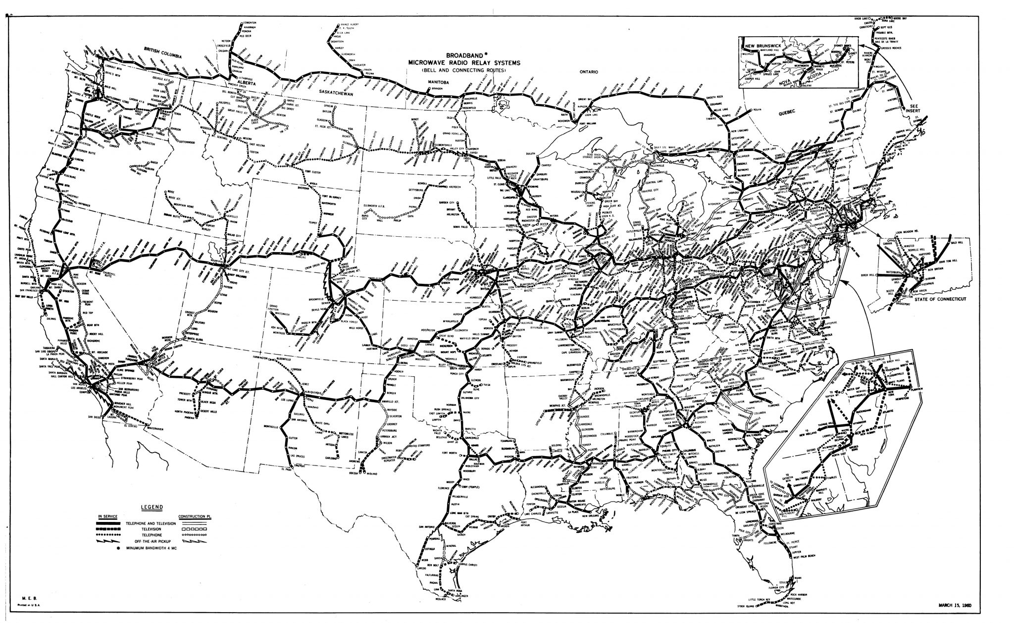
The public face of Long Lines after World War II was the microwave radio-relay “skyway”: thousands of towers, generally 25 to 40 miles apart, hopping 4 GHz and later 6 GHz beams from horn to horn across the continent. That radio web sat on top of an older and equally important buried plant: open-wire carrier routes from the early century, then coaxial L-carrier cables that by the 1960s were being laid in hardened trenches with underground main stations. Together they were the American long-distance backbone before satellites took some television and before fiber optics ate the analog routes in the 1980s and 1990s.
Long Lines was not a local exchange. It did not put a black rotary phone on your kitchen wall. It moved thousands of voice channels, television programs, teletype, and later data between cities, and it did so with a reliability doctrine that mixed ordinary telephone engineering with Cold War survivability.
WHY IT WAS BUILT
Three problems stacked on top of each other.
First, distance and volume. Open-wire carrier and early cable could cross the country, but they were hungry for right-of-way, slow to build over mountains, and limited in bandwidth. After the war the Bell System expected a surge in long-distance calling and a new product that needed a fat pipe: network television. A single TV channel ate the equivalent of hundreds of telephone circuits. Coaxial cable could carry that load, but stringing coaxial across the Rockies and buying a continuous strip of land from New York to San Francisco was expensive and slow.
Second, terrain. Microwave needs only a line of sight and a hilltop lease. Bell Labs had spent the war on radar. Klystrons, better tubes, and 4 GHz technique made a radio hop of about thirty miles practical. You could build a coast-to-coast radio route without a continuous ditch.
Third, the state. From the 1950s the same plant carried military and federal traffic. AUTOVON, the Automatic Voice Network, was in practice a shadow telephone system that AT&T built and ran for the Department of Defense on Long Lines transmission. Hardened coaxial routes and selected microwave stations were laid out so that a nuclear strike on cities would not automatically erase command circuits. Survivability was not a hobby. It was a design requirement written into Bell System Practices.
So Long Lines was built to make money on long-distance and television, to beat geography, and to keep talking after a bad day in the Cold War.
WHAT MAKES IT ROBUST
Robustness here means more than “the radio usually works.” The network was designed so that no single tower, no single cable cut, and no single city switch would take the country off the air.
Diversity of media. Microwave and coaxial ran in parallel. If a radio hop faded in rain or a tower was wrecked, traffic could be rolled onto cable, and the reverse. Routes were deliberately separated in miles so that one air burst would not kill two adjacent structures of the same hardness. Bell System Practice 001-780-201 laid out separation tables for 2 psi, 10 psi, and 50 psi buildings against a 10-megaton air burst.
Automatic protection. Radio channels had protection (hot standby) channels. If a transmitter died, the system switched. If a whole station died, switching centers could reroute groups and mastergroups around the hole. Portable microwave trailers existed for long outages. In 1961, after saboteurs wrecked a Utah repeater, Long Lines used that kind of patch.
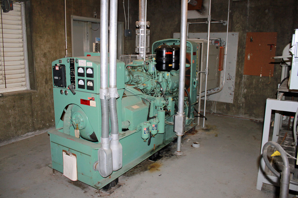
Power that does not trust the grid. Every serious site had batteries and diesel generators. Early TD-2 plants used large 130 V and 250 V battery strings for vacuum-tube plate supplies, plus filament batteries, with thyratron and selenium rectifiers. Generators were exercised on dummy loads. Dual sets often swapped roles on a schedule so both stayed proven. On hardened and semi-hardened buildings the generator air intake sat behind a concrete blast shield so a pressure wave would not smash the cooling path.
People and procedure. Many main stations were staffed. Unmanned repeaters were designed for long walks between visits, with alarms back to a control office. The culture was Bell System: documented practices, Western Electric hardware, spare parts in the building.
Hardening, described below, was the visible Cold War layer. The quieter layer was ordinary telephone conservatism: extra channels, extra routes, extra fuel, extra batteries.
TECHNOLOGY
Open wire and early cable. Before microwaves, Long Lines was copper. New York reached Denver by 1911. Repeaters pushed voice across the continent. Carrier systems stacked extra conversations on the same wires. This plant never fully vanished, but it ceased to be the high-capacity backbone.
L-carrier coaxial. Bell Labs tested coaxial between New York and Philadelphia in the mid-1930s. L-1 went into service Minneapolis–Stevens Point in 1941: about 600 voice channels per working tube, 3 MHz, repeaters every eight miles. After the war AT&T announced a national coaxial build for telephone and television. Successive systems packed more channels into higher frequencies and closer repeaters:
- L-1 (1941): ~3 MHz, ~8 mile repeaters, ~600 channels per tube - L-3 (1953): ~8 MHz, ~4 mile repeaters, ~1,860 channels per tube - L-4 (1967): ~17 MHz, ~2 mile repeaters, ~3,600 channels per tube - L-5 (1974): ~57 MHz, ~1 mile repeaters, ~10,800 channels per tube - L-5E (1975): ~66 MHz, ~13,200 channels per tube
A route used several working pairs plus protection pairs in one sheath. Published route capacities ran from a few thousand circuits on early L-1 to well over 100,000 on a full L-5E cable. In the 1960s the military-driven L-3I and later L-4/L-5 builds put terminals and repeaters in underground vaults. Buried coaxial itself was credited with surviving on the order of 150 psi overpressure. Standard repeater manholes were designed around 50 psi. Main stations were hardened to 10 or 50 psi depending on the route. Cable was typically four feet down. Side legs left the main trench to serve cities. AUTOVON rode these cables and shared spare capacity with civilian long distance.
Multiplex hierarchy mattered as much as the pipe. Voice channels were stacked into groups, supergroups, and mastergroups (Long Lines Type L-600 used 600-channel mastergroups). That analog multiplex is why one radio channel or one coaxial tube could look like a thousand telephone calls.
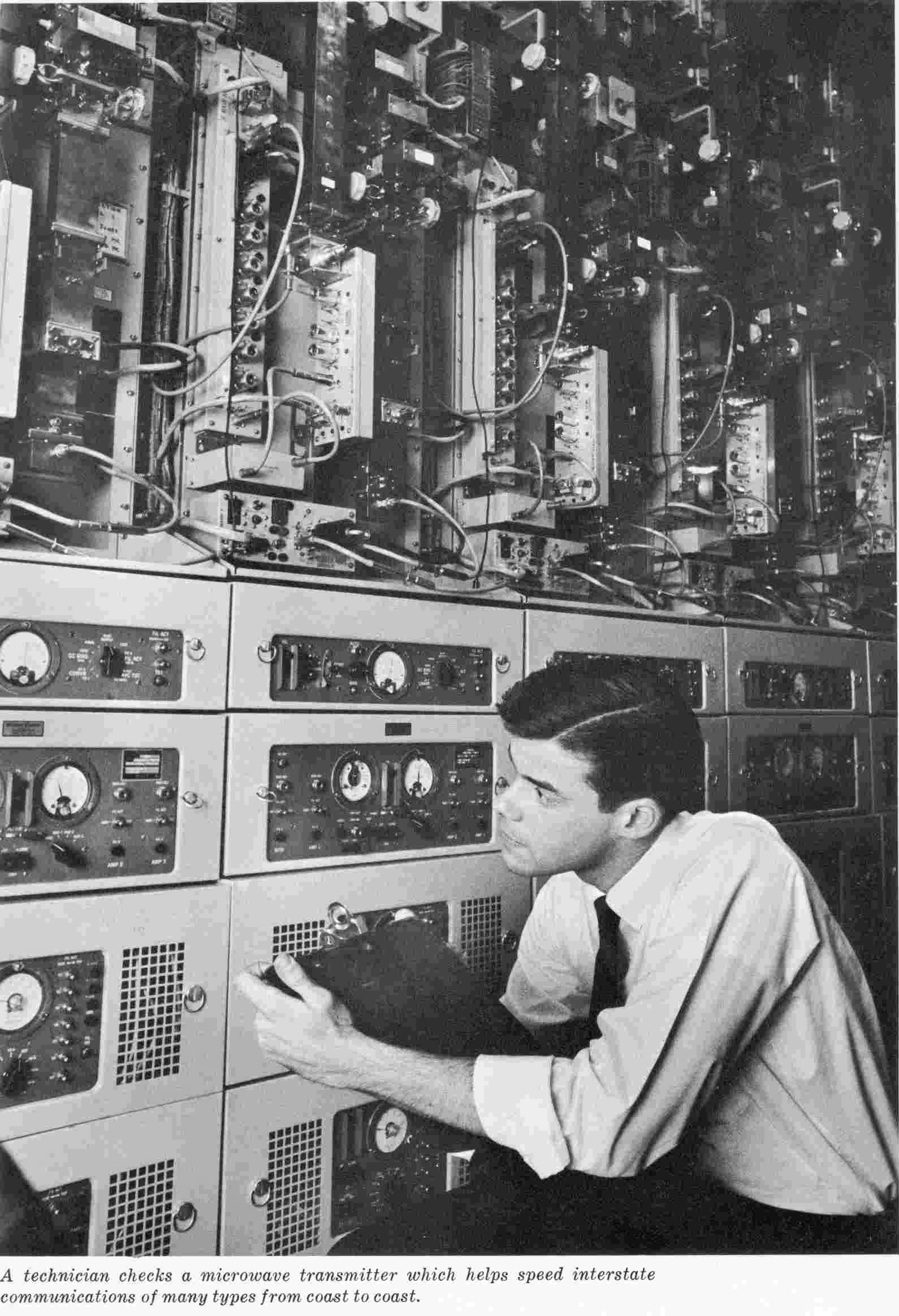
Microwave radio: TDX, TD-2, TD-3, TH. The experimental TDX link New York–Boston opened commercially in 1947 after a 1946 Murray Hill trial. Four channels near 4 GHz, each able to carry hundreds of telephone circuits or one television signal. The FCC set aside 3.7–4.2 GHz for the common-carrier radio relay service.
TD-2 was the production workhorse. Coast-to-coast service opened 17 August 1951 on a chain of 107 towers that had cost about $40 million and three years to build. First call that day; first transcontinental television on 4 September 1951, President Truman opening the Japanese Peace Treaty conference in San Francisco. Early TD-2 used Western Electric 416-series “Morton” tubes in the transmitters. Tube life was a running battle: a few thousand hours at the start, tens of thousands by the late 1960s after Bell Labs and Western Electric worked the 416. Capacity grew from a few hundred circuits per radio channel to 600, then 900 (TD-2A plant and antenna improvements), then 1,200 on solid-state TD-3, with later analog loading quoted still higher as noise and antennas improved.
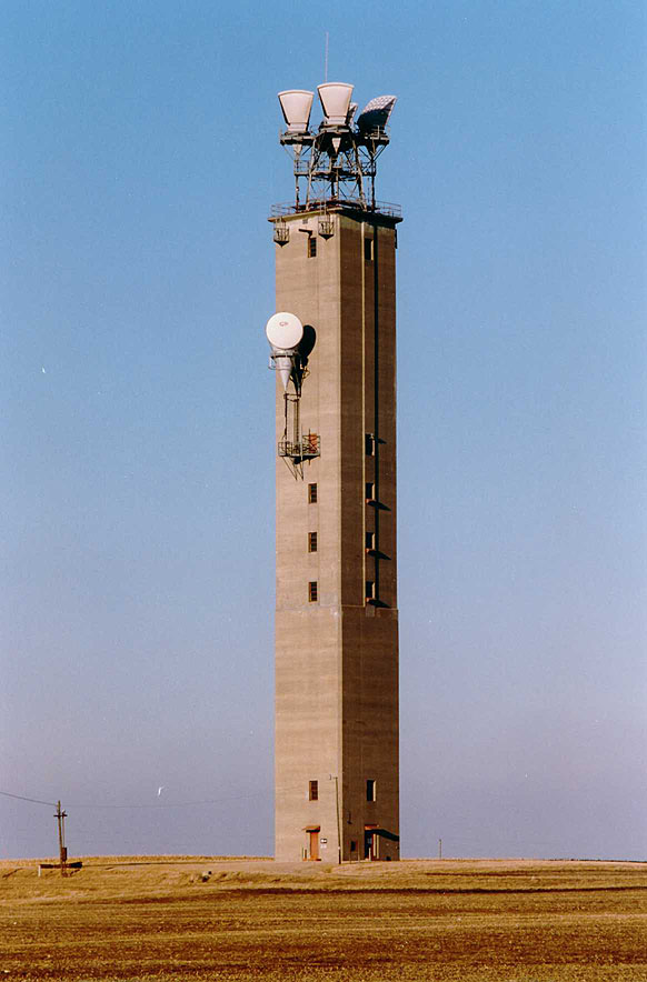
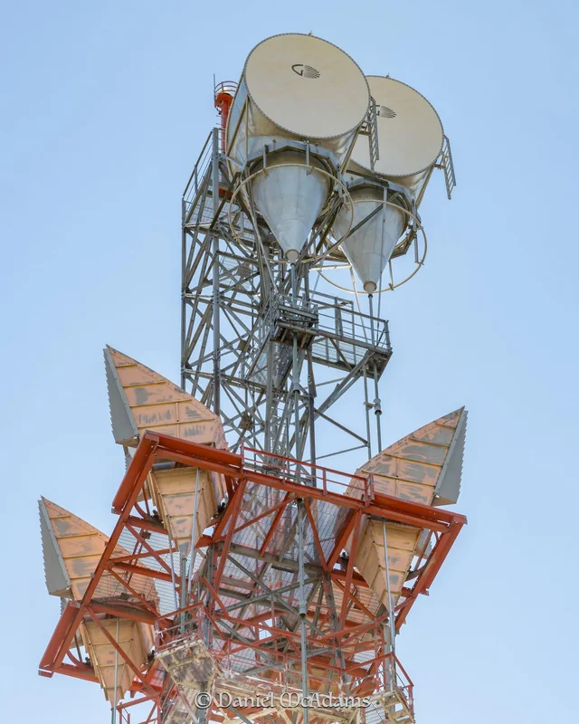
TH added the 6 GHz band and polarization tricks so two signals could share a horn. Stations after the mid-1950s standardized on the KS-15676 horn-reflector antenna: a large aluminum “sugar scoop” that could handle several bands at once and keep rain and side lobes under control. Polarization expanded capacity without a second tower. Waveguide runs were kept short — Long Lines treated about 100 feet as a practical limit because of loss and echo — which is one reason some early concrete towers put the radio room high in the shaft instead of on the ground.
By the late 1960s observers estimated that roughly 40 percent of long-distance calls and 95 percent of intercity television rode the microwave plant. Digital-under-voice later stuffed data under analog radio. Fiber and satellites then made the analog radio obsolete.
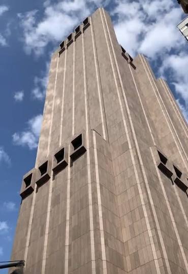
Switching and special networks. Long Lines connected to crossbar and later ESS machines. AUTOVON used four-wire No. 5 crossbar, then 1ESS, with multilevel precedence and preemption (Routine, Priority, Immediate, Flash, Flash Override). Greenbrier (Project Greek Island) was a congressional relocation bunker with a hidden Long Lines/Bell presence. 33 Thomas Street in Manhattan — the windowless “Long Lines Building” — is the urban extreme of the same idea: a switching and gateway fortress rather than a hilltop repeater.
HOW THE MICROWAVE TOWER SITES WERE BUILT, AND WHY THEY WERE BUILT THAT HARD
A typical postwar radio station is a package: land on a ridge or a purpose-built pad, a tower or self-supporting concrete shaft, a windowless equipment building, horns or later dish antennas, waveguide, batteries, diesels, fuel, and a fence. Spacing followed line of sight and Fresnel clearance, usually 30 to 40 miles, with doglegs so adjacent paths would not interfere and so one blast would not take two hops.
Early concrete towers. The first transcontinental radio route used a family of square reinforced-concrete towers, Types 1 through 4D. Walls a foot thick or more. Plan about 24 to 27 feet square. Forty-nine of these shafts were built — most from Thomas Hill toward Collins, plus a handful in Ohio, New York, and one at Vernal. Postwar steel was scarce and expensive; concrete was available; and putting the radio room up in the tower shortened waveguide. Types 1–3A stacked radio, high-voltage batteries, and filament batteries under the roof, generator on the ground. Later types froze the radio floor around 103 feet because fourteen flights was judged enough for a technician and because waveguide above that hurt the signal. Some used slip-form construction to 190 feet. Demolition later proved how stout they were. Sideling Hill did not come down on the first try.
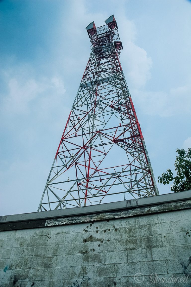
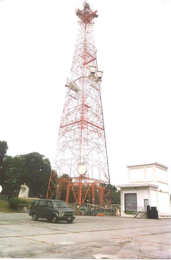
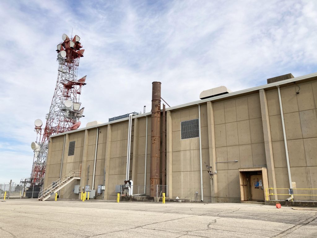
Steel towers and ground buildings. Most of the later network used lattice or tapered steel towers with a separate one-story or two-story building at the base. Horns sat on a main platform, sometimes with an upper deck. Western Electric supplied radios, power, and often the tower steel through contractors. Heights from under 100 feet on a mountain to 300-plus feet on flat land.
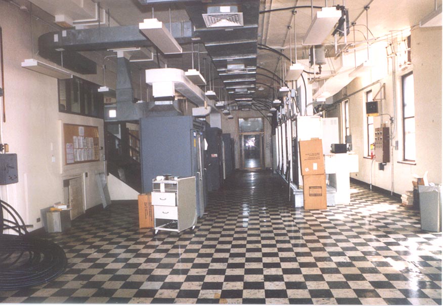
Semi-hardened concrete buildings. From the late 1950s through the 1960s many new stations were poured as windowless concrete boxes: 12-inch or thicker reinforced walls, few openings, louvers instead of glass. These were not city-killer bunkers. They were rated for distant overpressure, commonly discussed as 2 psi on many radio routes, with 1/2 psi allowed where the threat and cost justified a lighter shell. Openings got blast closures. Generator intakes sat behind masonry blast shields. Pneumatic or motorized steel shutters could seal the building. Some sites had a five-minute sequence so HVAC could be secured before the doors slammed. Decontamination showers, CBR filters, and automatic seal-on-detonation logic showed up at the more serious stations (Durham, Connecticut is a documented example). Equipment was hard-mounted. The point was not to sit under a fireball. The point was to ride out a distant burst, EMP-ish coupling, broken commercial power, and fallout long enough to keep the hop alive.
Why harden a radio site at all? The tower and the sheet-metal horns were the weak parts. A blast wave and flying debris love a 200-foot mast and a thin aluminum scoop. Buried coaxial was the true hard path: earth cover, 150 psi cable, 50 psi manholes, 10–50 psi main stations with blast locks (two vault doors, only one open at a time), spring-mounted racks, Faraday and grounding practice against EMP and lightning. Microwave was faster and cheaper to build, so it became the everyday workhorse. Hardening the base building, the power plant, and the route geometry was how Long Lines made radio “good enough” for government traffic without pretending a KS-15676 horn would survive Ground Zero.
On some AUTOVON interconnects even the horns were given extra metal as a gesture at overpressure. Waveguide penetrations were bonded and grounded because a tower is also an EMP and lightning antenna; military studies later judged TD-2 practice against lightning transients to be in the same league as expected HEMP conducted stress on the waveguide.
Underground coaxial main stations. A different animal from a hilltop repeater. Pottstown, Pennsylvania is a clean published example: two reinforced-concrete underground buildings under about three feet of earth and a parking lot, surface headhouse with garage bays, stair and hoist shafts, motorized blast doors in a blast lock. Staff lived with the machines. Similar holes were punched along L-3I and L-4/L-5 routes from the mid-Atlantic to California. Peak plant: on the order of 100 hardened main stations, a thousand repeater vaults, and thousands of miles of right-of-way. Fairview, Kansas and Conyers/Rockdale, Georgia turn up in lists as emergency control or SCAN/alternate national nodes. That is Long Lines as a war circuit, not as a TV hop.
Fuel, water, toilets, and food at staffed hardened sites were sized like a small fallout shelter because the doctrine assumed the crew might have to stay.
HISTORY
1911 — Long-distance wire reaches Denver.
1929–1936 — Bell Labs coaxial experiments; New York–Philadelphia semi-commercial coaxial with repeaters.
1941 — First production L-1, Minneapolis–Stevens Point. War stops the wide build.
1943–1947 — Bell Labs plans a New York–Boston microwave trial. Construction of TDX starts 1945. Commercial New York–Boston radio, 1947. Brochure language of the period: “seven towers on seven hilltops.”
1948–1951 — L-1 coaxial grows along the East Coast and west toward Chicago and St. Louis. TD-2 engineering. Transcontinental microwave completed. 17 August 1951: first coast-to-coast radio-relay telephone call. 4 September 1951: Truman on live transcontinental television.
1953 onward — L-3 coaxial. TD-2 capacity upgrades. KS-15676 horns from the mid-1950s. Network spreads into a grid, not a single spine. Junction stations where several radio routes meet. Television operating centers ride the same radios.
Early 1960s — AUTOVON construction. Hardened L-3I transcontinental cable for the military, also carrying civilian overflow. Semi-hardened radio buildings become common on new routes. TD-3 solid-state program authorized 1962.
1967 — L-4. Long Lines runs a coast-to-coast TD-2 evaluation over 122 stations.
1974–1976 — L-5 and L-5E, last analog coaxial generation. First commercial L-5 route Lillyville, Pennsylvania to Hillsboro, Missouri. Many older cables are never upgraded because fiber is already visible.
1984 — Bell System divestiture. Long Lines becomes the skeleton of AT&T Communications. Radios begin to be “turned down” as fiber is lit.
Late 1980s–1990s — Analog microwave dies in pieces. A few hops go digital and last longer. AT&T sells large parts of the tower fleet around 1999. American Tower and other landlords inherit steel and concrete. Horns come down or rust. Fiber and later cellular tenants reuse some sites because a hill that was useful in 1958 is still useful.
What remains is archaeology: sugar-scoop horns on a Midwest tower, a blast shield over a generator intake, a parking lot that is secretly a roof, a windowless cube off a county road.
WHAT IT CARRIED
Ordinary long-distance calls. Network television from the Kennedy assassination coverage through the network era. Radio network feeds. Government voice, AUTOVON, and associated data. Later, pieces of digital service stuffed under analog radio. The same physical route could be civilian by day and a military precedence call at night. That dual use is why a telephone company poured two-foot concrete and bought diesel by the tank.
LIMITS
Microwave is line of sight. Weather fades 6 GHz worse than 4 GHz. A tower is a target for weather, vandals, and blast. Coaxial is slow to splice and hungry for repeaters. Analog multiplex does not scale like a modern fiber wavelength. Hardening was always a compromise: good against a distant burst, not a silo-buster on the parking lot. Once fiber offered orders of magnitude more bandwidth at lower operating cost, the analog skyway had no commercial reason to live.
STATUS
The Long Lines Department as a Bell System organ is gone. The analog radio network is dead except for trivia. Buried coaxial still exists as right-of-way and sometimes as dark or abandoned plant. Towers still punctuate ridgelines because steel is useful. The method — diverse routes, protected channels, on-site power, and buildings that assume the grid and the city may fail — is the part that survived into later networks, even if the horns did not.
IN ONE SENTENCE
AT&T Long Lines was the Bell System’s national long-haul plant — coaxial cables in hardened ground and a continent of microwave towers with self-powered, often blast-baffled buildings — built to carry telephone calls and television in peacetime and to keep government circuits alive if the cities burned.