WHAT IT IS
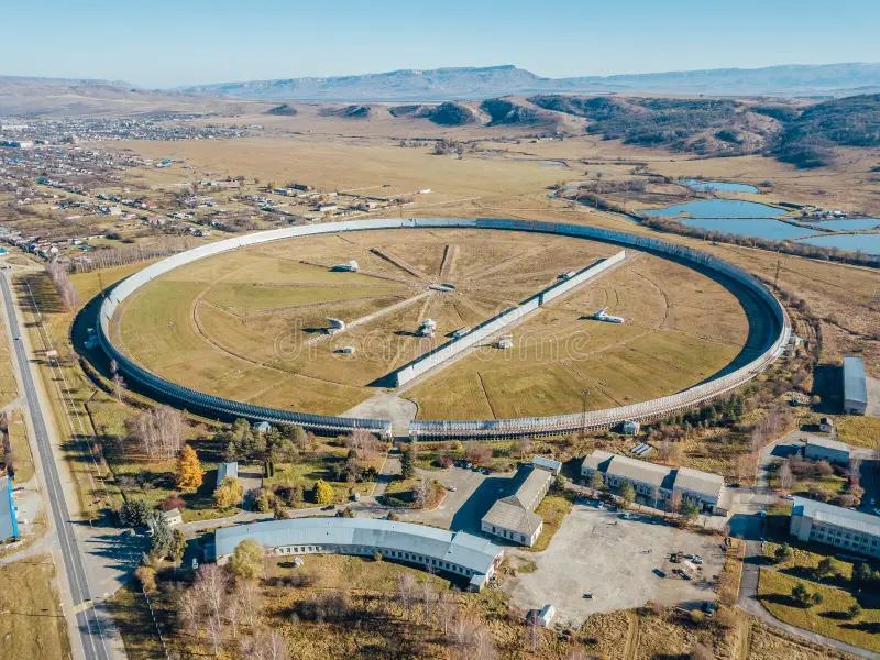
RATAN-600 (Russian: РАТАН-600, Радиоастрономический телескоп Академии наук – 600, Radio Astronomical Telescope of the Academy of Sciences, 600 m) is a ring-shaped radio telescope of the Special Astrophysical Observatory of the Russian Academy of Sciences (САО РАН, Специальная астрофизическая обсерватория) near the settlement of Zelenchukskaya (станица Зеленчукская), Zelenchuksky District, Karachay-Cherkessia, Russia. Its main reflector is a circle 576 m in diameter assembled from 895 separately adjustable rectangular reflecting panels. It is generally described as the largest-diameter individual radio telescope in the world.
The instrument is not a filled dish. It is a variable-profile antenna: the panels stand on the ground in a ring and are re-aimed individually so that any chosen arc of the ring acts as a segment of a very large paraboloid. The geometric collecting area is quoted as about 12,000 m² (four sectors of about 3,000 m² each). The beam is knife-shaped rather than pencil-shaped, a property that shapes how every observation is made and processed. The telescope works mainly as a transit instrument: the sky drifts through the beam as the Earth rotates.
The telescope covers roughly 0.6 to 35 GHz (about 0.8 to 50 cm wavelength in the SAO general description), with the heaviest use in the centimetre band. It is operated as a common-user facility. Observing time is allocated by a programme committee, and the SAO description states that applications typically exceed available time about threefold.
DEVELOPMENT
The underlying idea, an antenna whose reflecting surface is built from many movable strips so that its profile can be changed for different source elevations, is credited to Semyon Khaikin (Семён Хайкин) and Naum Kaidanovsky (Наум Кайдановский). It was first built as the Big Pulkovo Radio Telescope (Большой Пулковский радиотелескоп, BPR) at Pulkovo Observatory, where the reflector was adjusted manually. The success of that design led to the larger RATAN-600.
The design assignment was prepared by the Main Astronomical Observatory of the USSR Academy of Sciences (Главная астрономическая обсерватория, Pulkovo). The project was approved on 18 August 1965 by order No. 53-1366 of the Presidium of the Academy of Sciences, and on 6 October 1965 a site was allotted on the plain between the Bolshoi Zelenchuk and Khusa-Kardonikskaya rivers near Zelenchukskaya. A Council of Ministers resolution on building a large radio telescope followed in 1966. The technical assignment was approved in March 1968 and construction began that summer on the southern edge of the settlement. In 1969 the project was incorporated into the Special Astrophysical Laboratory (later the Special Astrophysical Observatory). D. V. Korolkov (Д. В. Корольков) is named as chief designer for the radio-electronic equipment.
The first stage, the Northern sector of the circular reflector with feed cabin No. 1 and laboratory building, was completed in 1973 and accepted for commissioning in January 1974. A Department of Radio Astronomical Observations was formed under Yuri Pariisky (Юрий Парийский). The first observation took place on 12 July 1974 on the Northern sector: the source PKS 0521-36 at 3.9 cm. Regular observations began in 1975, with annual programmes approved by the RATAN-600 Programme Committee chaired by Nikolai Kardashev (Николай Кардашёв). Construction of the remaining parts, the Western, Eastern and Southern sectors and the flat reflector, was completed in December 1976. Sources differ on the "opening" year: 1974 is the date of first light and first observations, while 1977 is sometimes given as the date of full operation.
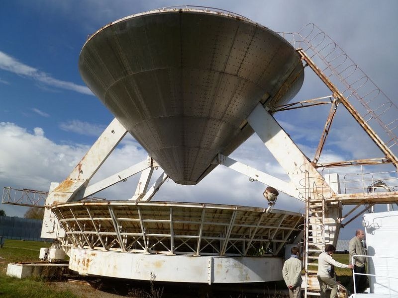
In late 1985 an additional conical secondary reflector (feed cabin No. 6) was installed, allowing the full ring to be used.
A group of staff of the Special Astrophysical Laboratory who designed and built the instrument was awarded Soviet orders and medals in 1978.
SITE
RATAN-600 stands at about 43°49′33″ N, 41°35′E (sources give 41°35′11″ and 41°35′14″ E) at an altitude of 970 m, in the northern foothills of the Greater Caucasus. The same observatory complex includes the 6 m optical telescope BTA-6 (БТА, Большой телескоп альт-азимутальный), which is a few kilometres away. About 4.5 km to the south is the Zelenchukskaya radio astronomical observatory of the Institute of Applied Astronomy (ИПА РАН) with its fully steerable 32 m radio telescope RTF-32.
Because the ring is a flat circular installation standing on a plain, the site is exposed to man-made radio interference. SAO RAS describes interference protection, including active suppression at decimetre wavelengths, as an ongoing part of receiver development.
HOW IT WORKS
A conventional paraboloid with a resolution at centimetre wavelengths comparable to RATAN-600 would need a dish hundreds of metres across on a tall support structure, which is very expensive. RATAN-600 instead keeps the reflector close to the ground. The reflector is made of vertical strips placed along a curve that is the intersection of an imaginary paraboloid, aimed at the source, with a horizontal plane through its focus. That section is a circle when the paraboloid points at the zenith, a parabola when it points at the horizon, and an ellipse at intermediate elevations. Calculations showed that the displacement of the panels needed to retarget between sources is modest, which allowed relatively simple, inexpensive mechanisms. In the original design the panels were controlled semi-automatically, and later the control was made fully automatic.
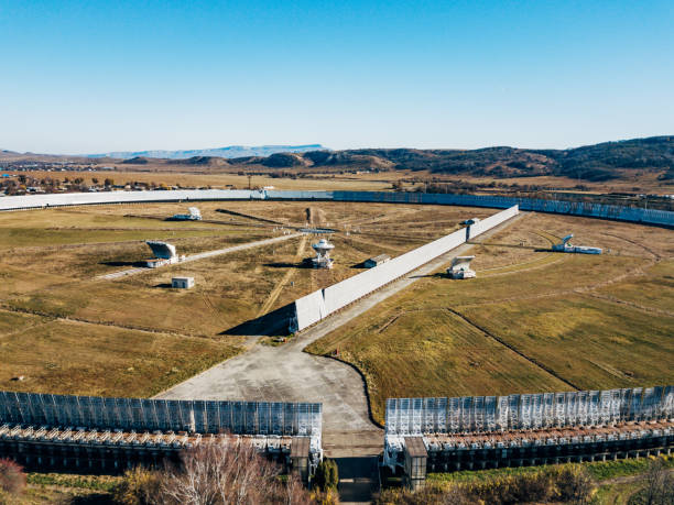
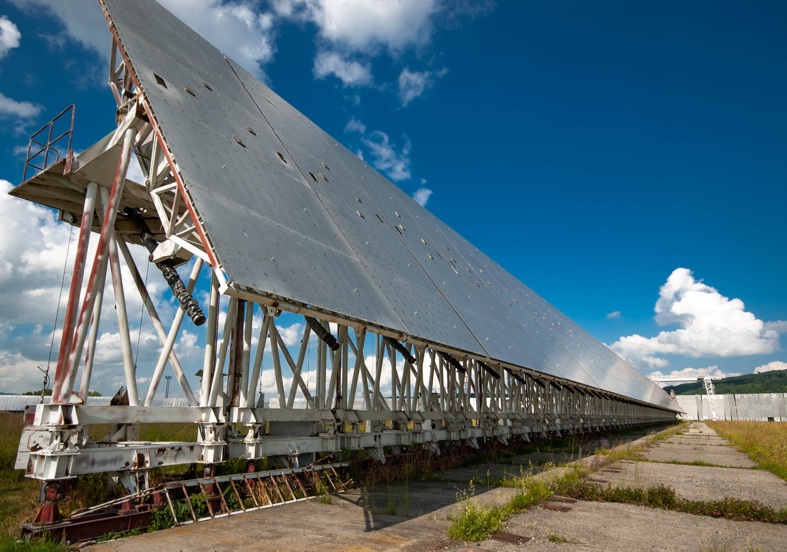
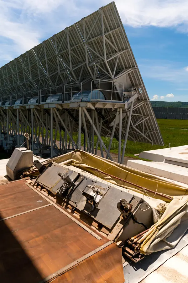
CIRCULAR REFLECTOR (круговой отражатель). The ring consists of 895 rectangular elements, each about 11.4 × 2 m (the SAO handbook gives 2 × 11.5 m). The central part of each panel, 5 m high, has a radius of curvature of 290 m and is made to higher accuracy. Each element can be moved in three degrees of freedom. The ring is divided into four independent sectors named by compass direction: Southern (южный), Northern (северный), Eastern (восточный) and Western (западный), each of about 225 elements and about 3,000 m² (4 × 3,000 = 12,000 m²). Elements of one sector are set along a parabola to form a focusing strip, and the feed is placed at its focus.
FLAT REFLECTOR (плоский отражатель). The flat reflector is a line of 124 plane elements, each 8.5 m high, with a total length of about 400 m. Elements rotate about a horizontal axis near ground level. For some observations the flat reflector can be laid down flat to the plane of the ground. It acts as a periscope mirror: radiation falling on it is sent to the Southern sector of the ring, which focuses it on a feed. This is the arrangement known in the West as a Kraus-type periscope, after the Ohio State University "Big Ear" design. By positioning the feed and retuning the mirrors the beam can be pointed at a chosen elevation, and source tracking is possible with the feed moving continuously while the mirrors are retuned.
SECONDARY MIRRORS AND FEED CABINS (приёмные кабины). The ring focuses radiation onto secondary mirrors (вторичные зеркала), each paired with a feed cabin carrying receivers. The cabins stand on railway platforms. A central turntable (центральный поворотный круг) distributes them among 12 radial rail tracks, giving fixed azimuths in 30° steps, and annular (arc) rails allow movement between azimuths. According to the 1997–1998 handbook, only azimuths 0°, 30°, 180° and 270° were in use at that time. Cabins 1 to 4 carry parabolic-cylinder secondary mirrors. Cabin No. 5 has a larger secondary mirror, designed for efficient use with the "flaps" of the ring, and can move along radial and arc tracks, so that a source can be followed for a long time. Cabin No. 6 has a conical secondary mirror above the feed and uses the whole ring. It is the instrument most often shown in photographs and appeared on a 1987 USSR postage stamp.
BEAM SHAPE. The pattern is knife-shaped: very narrow in the horizontal direction and wide in the vertical, so one pass gives a one-dimensional brightness profile along the scan. The distribution across the strip in the other dimension is recovered from observations taken at several azimuths while the source moves vertically.
TECHNICAL SPECIFICATIONS
Main ring diameter: 576 m. Number of elements: 895. Element size: about 11.4 × 2 m. Geometric area: about 12,000 m² (four sectors of about 3,000 m²). Flat reflector: 124 elements, 8.5 m high, about 400 m long. Altitude: 970 m. Operating range: about 610 MHz to 35 GHz (SAO general description, wavelength 0.8–50 cm). Maximum angular resolution: 1.7″ (published by SAO; other texts say "up to about 2 arcseconds"). Coordinate accuracy: 1–10″. Quoted flux-density limit: about 0.5 mJy. Quoted brightness-temperature limit: about 0.05 mK. Tracking time using Southern sector plus flat reflector: 1–3 hours. A resolution of about 1 arcminute in the horizontal plane at 8 cm is also quoted.
Conical mode (cabin No. 6): the whole ring is used, but only sources within ±5° of the zenith are observed, which at the site latitude corresponds to declinations of about 38° to 49°. This mode gives the highest resolution of the telescope.
Note on the area figure: some Western-language summaries give an effective area of about 1,000 m² for the ring, or element dimensions of 2 × 7.4 m. These conflict with SAO-derived Russian sources and are not used here.
RECEIVERS AND WAVELENGTHS
HISTORICAL SET. The 1996–1998 continuum handbook lists the classic single-channel radiometers (system noise temperature Tsys in K, 1σ sensitivity for 1 s integration):
1.38 cm (21.7 GHz): 1400 MHz band, Tsys 200 K, 1σ 15 mK. 2.70 cm (11.2 GHz): 1000 MHz, 140 K, 4 mK. 3.90 cm (7.7 GHz): 700 MHz, 140 K, 6 mK. 7.6 cm (3.95 GHz): 500 MHz, 40 K, 2.5 mK. 13 cm (2.3 GHz): 250 MHz, 60 K, 25 mK. 31.1 cm (0.985 GHz): 100 MHz, 100 K, 25 mK.
The 31 cm radiometer received a four-channel 30 MHz-band signal processor in March 1996 with on-line impulse-interference removal, and high-rate recording (100–1000 Hz) allowed trial pulsar observations (PSR 0950+08, PSR 1133+16). A "sliding" recording mode allowed a source to be followed for 100–150 s.
CURRENT COMPLEXES. SAO RAS notices to users for 2024 list: (1) a continuum radiometer complex covering 1.25–22.3 GHz at 1.25, 2.25, 4.7, 8.2, 11.2, 14.4 and 22.3 GHz on secondary mirror No. 1, with fractional bandwidths from about 4 % (decimetre) to 12 %; (2) a 4.7–22.3 GHz continuum complex on secondary mirror No. 2; (3) a multi-beam 2.25, 4.7 and 14.4 GHz complex for fast radio burst searches on secondary mirror No. 5; (4) a solar spectral-polarization complex for 3–18 GHz and (5) another for 1–3 GHz, both on secondary mirror No. 3; (6) a test-mode continuum complex at 4.7, 8.2 and 30 GHz on mirror No. 3. All continuum receivers are direct-amplification total-power radiometers with square-law detection, using uncooled HEMT amplifiers and the ER-DAS data acquisition system (Embedded Radiometric Data Acquisition System). Published flux-density sensitivities per beam from the committee circular include about 200 mJy at 1.25 GHz, 40 mJy at 2.25 GHz, 5 mJy at 4.7 GHz, 10 mJy at 8.2 GHz, 15 mJy at 11.2 GHz and 50 mJy at 22.3 GHz. A 2025 SAO paper reports that around 23 radiometers (35 frequency channels) operate around the clock.
The fast-burst complex uses a 600 MHz band split into four 150 MHz sub-bands for each of 4 radiometers on the Western sector (16 independent radiometers), recorded at 16384 samples per second per channel. The four beams watch four adjacent parts of the sky at once, and the sub-band delay lets dispersion by the interstellar medium be measured, which helps distinguish distant sources from local interference.
OBSERVING MODES
TRANSIT. The standard mode: the ring is fixed on a chosen declination and the Earth's rotation sweeps the source through the beam, giving a one-dimensional scan. The recorded profile is the sky brightness convolved with the beam.
SECTOR MODES. Two-mirror system: one sector of the ring focuses radiation onto the cylindrical secondary mirror and feed (Northern sector at azimuth 0°, Southern sector at 0° or 180°, and so on). Three-mirror system: the flat reflector sends radiation to the Southern sector, which focuses it onto a secondary mirror and feed (Kraus-type periscope). This is the "South + Flat" mode, which also allows tracking for 1–3 hours. Entire ring: the conical secondary mirror (cabin No. 6) uses all sectors near the zenith.
SIMULTANEOUS AND MULTI-AZIMUTH OBSERVATIONS. Several sectors can be coupled to separate secondary mirrors, so independent programmes can run at the same time. Observing the same object at several azimuths gives scans at different position angles and allows reconstruction of two-dimensional brightness distributions. Solar observations are routinely made in multi-azimuth form: SAO schedule text refers to 13-azimuth solar observations, and 3-azimuth programmes appear in the schedules.
SURVEYS. Round-the-clock fixed-declination drift scans in the radio continuum are used for sky surveys and monitoring. SAO RAS reported over 50,000 continuum observations by the late 1990s.
MAJOR RESULTS
RATAN-600 has operated for decades in high demand. Its stated main advantages are multi-frequency capability and high brightness-temperature sensitivity.
SOLAR RADIO ASTRONOMY. Observation of the solar corona at radio wavelengths is a long-standing programme. Multi-azimuth, spectral and polarization observations are used to study active regions, local sources, magnetic fields and flare phenomena. The 1–3 GHz panoramic spectral complex has been used to study low-contrast coronal structures. SAO RAS reports a software package, RatanSunPy, for processing RATAN-600 solar data, including automatic detection of local sources and matching them with NOAA active regions, relevant to space-weather forecasting.
APOLLO TRANSMITTERS (1977). In October–November 1977 observations were made of the ALSEP transmitters left on the Moon by Apollo missions 12, 14, 15, 16 and 17. Selenographic coordinates of the sites (accuracy about 1°) and the transmitter power were measured and found consistent with NASA data (Naugolnaya et al., Pisma v Astronomicheskii Zhurnal vol. 4, 1978).
SOURCE SURVEYS AND MONITORING. Programmes include surveys of radio sources, monitoring of blazars and quasars, galactic and microquasar variability (the schedule lists monitoring of X-ray binaries with relativistic jets), studies of interstellar scattering, and searches for fast radio bursts and transients. Joint programmes with institutes in China, India, the UK and other countries are listed in the 2026 schedule.
HD 164595 SIGNAL (2015). See next section.
ROLE IN SETI AND OTHER USES
Detection of artificial signals of extraterrestrial origin was one of the stated goals of RATAN-600. On 15 May 2015, during a SETI-related monitoring programme, the telescope recorded a signal of about 0.75 Jy at 2.7 cm (11 GHz) in the direction of the star HD 164595 in Hercules. The profile as the beam passed matched the response expected from a distant source. The detection was announced in late August 2016 as a request for follow-up. On 1 September 2016 SAO RAS stated in an official comment that processing and analysis indicated the signal was most probably of terrestrial origin. Other observatories did not confirm it. Speculation about a classified satellite is not established.
Other uses listed by SAO include study of the Solar System bodies, solar wind (interplanetary scintillation), planets, radio galaxies, quasars and the cosmic microwave background as capabilities. Reported CMB work has mainly been experimental and instrumental, such as test 30 GHz receiver arrays and beam-pattern studies, rather than a completed major CMB result.
UPGRADES
Late 20th century: extensive modernization, with many functions of the telescope automated. In 2015 the Ministry of Education and Science (Минобрнауки) allocated 100 million roubles for automation and renovation of the drive and support system of the reflector, including control of panel tilt. Officials stated in July 2015 that the work was planned to take two years.
2020s: renewal of the receiver base, ER-DAS acquisition, and new radiometers. A dual-band decimetre radiometer for 1.45 and 2.35 GHz (100 MHz bands, a common phase centre horn, Micran uncooled amplifiers with 38 dB gain and 0.5 dB noise figure) replaced the older 13 cm and 25 cm receivers; the longest wavelength was changed from 25 cm to 21 cm (the new 1400–1500 MHz range replaced 1220–1270 MHz). Flux-density sensitivity of 10–20 mJy was reported in these bands. Planned: neutral-hydrogen 21 cm spectral observations, active digital interference suppression, and pulsar and FRB work.
STATUS
RATAN-600 is operating. SAO RAS publishes half-year observing schedules, including for 2026, with programmes allocated among feed cabins 1, 2, 3 and 5. Its main work is solar studies, continuum surveys and monitoring of compact radio sources, and transient searches. Upgrades of receivers and electronics continue. The mechanical ring and flat reflector are the original 1970s structures with later automation.
IN ONE SENTENCE
RATAN-600 is a 576 m ring of 895 adjustable panels at Zelenchukskaya that works as a transit radio telescope, using the ring, a flat periscope reflector and movable secondary-mirror cabins to give a very narrow knife-shaped beam, high brightness-temperature sensitivity and multi-frequency coverage from about 0.6 to 35 GHz.