WHAT IT IS
The Mark 38 Gun Fire Control System (GFCS) is the U.S. Navy’s World War II–era main-battery fire-control plant for fast battleships and large cruisers. It is not a gun. It is the chain that turns “that ship is over there” into continuous train and elevation orders for 16-inch and 12-inch turrets, including when the firing ship is rolling, the target is moving, and the projectile will be in the air for more than a minute.
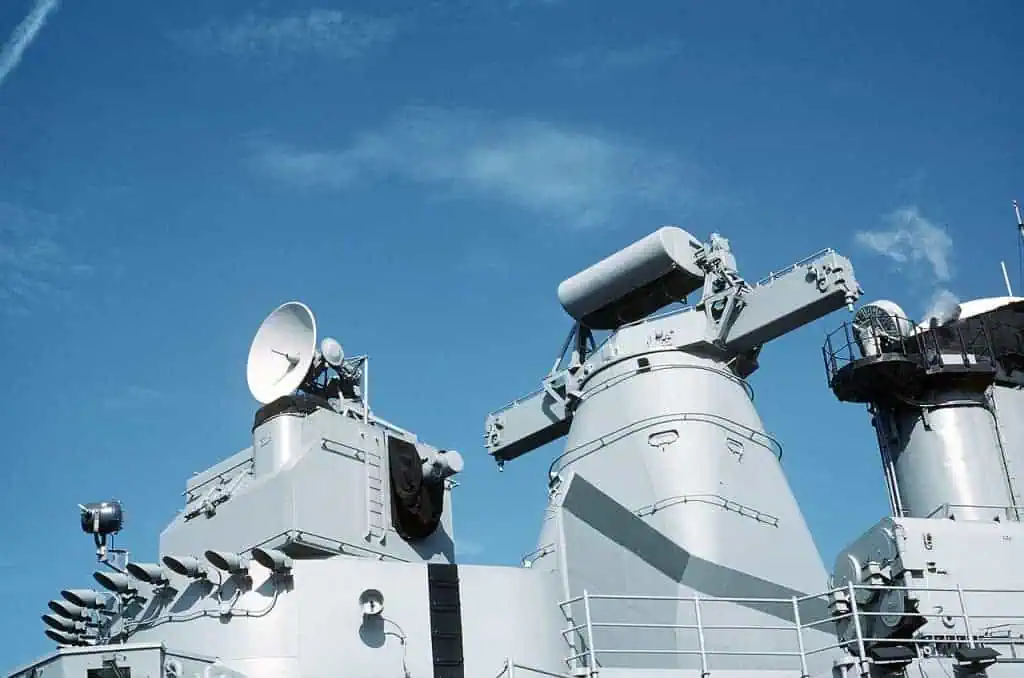
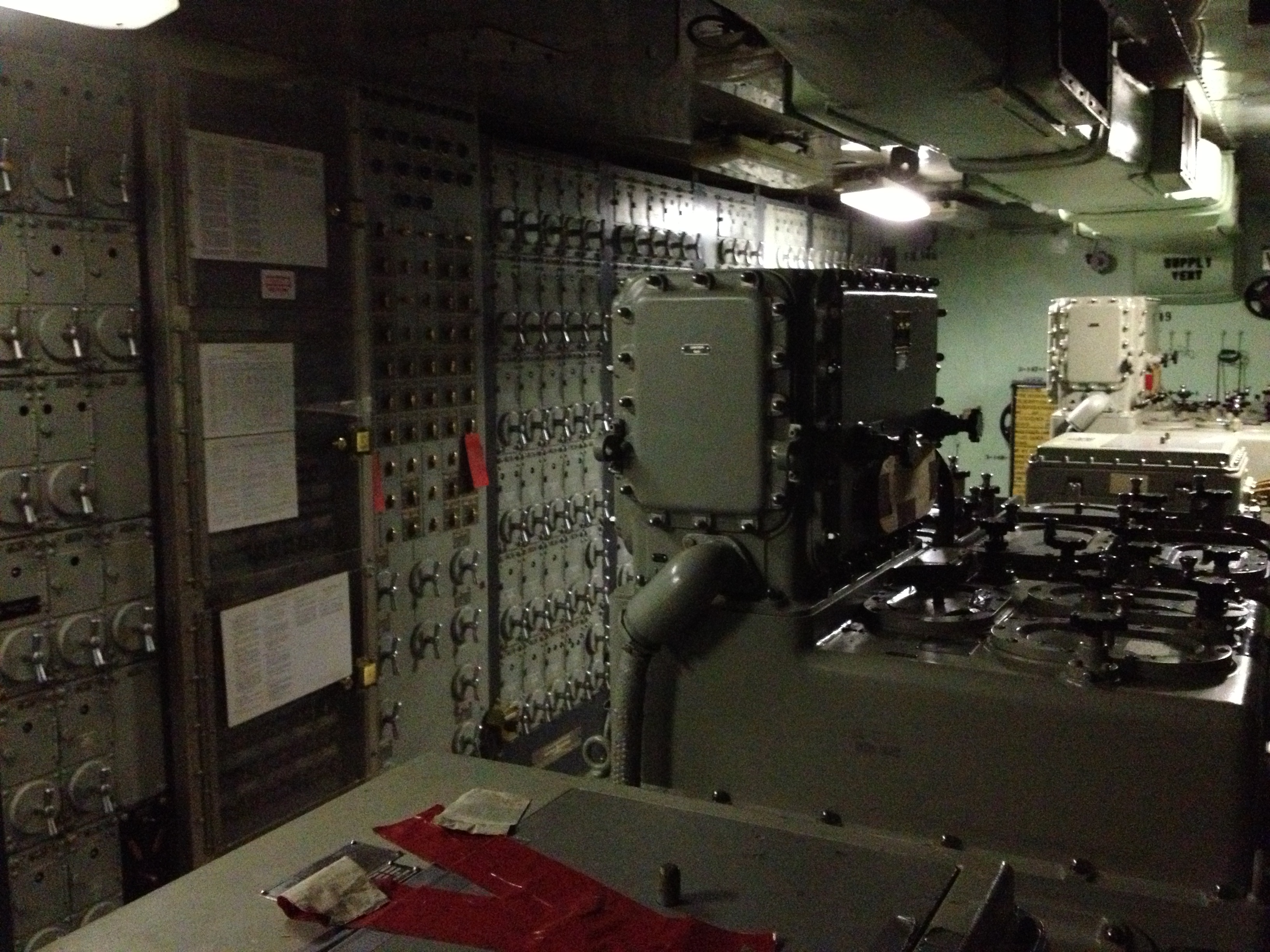
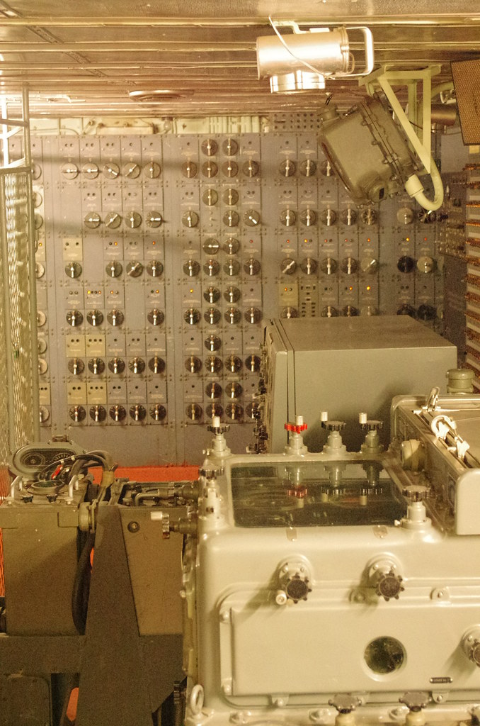
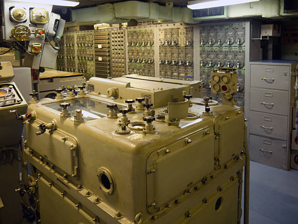
Three rooms do the work: a Mark 38 director high on the fire-control tower (Spot 1 forward, Spot 2 aft), a plotting room under armor with the Ford Instrument Mark 8 Rangekeeper and a Mark 41 or Mark 43 Stable Vertical, and the turrets themselves, which follow synchro gun orders through amplidyne / receiver-regulator power drives. Radar (first Mark 8, then Mark 13) sits on the director roof. Optical rangefinders stay as backup. Two complete systems, forward and aft, can run independently or be cross-connected at the fire-control switchboard.
It is not the modern Mark 38 25 mm Machine Gun System (M242 Bushmaster on a Mk 88 / Typhoon mount). Same Bureau of Ordnance number family; different century and problem.
WHAT IT IS USED FOR
Surface action against ships, and later naval gunfire support against shore. The Mk 38 plant is a linear-rate / generated-bearing surface system. It does not solve the full dual-purpose antiaircraft problem that the Mark 37 GFCS + Ford Mk 1A computer solves for the 5"/38 battery. Main-battery guns can be pointed at aircraft in a pinch; that is not the design job.
With radar, the plant can fire over the visual horizon, at night, and through smoke. Fall of shot is spotted on the B-scope and fed back as range and deflection spots. The same computer keeps a solution while own ship maneuvers because course, speed, and deck tilt are live inputs, not a frozen plot.
SHIPS
NavPers / Bureau of Ordnance: Gun Directors Mark 38 with Rangefinders Mark 48 on North Carolina, South Dakota, and Iowa class battleships and Alaska class large cruisers. Heavy cruisers generally used the related Mark 34 director (Mk 54 on Des Moines / Salem for a more AA-capable main battery). Radar Mark 13 (or earlier Mark 8) rides those directors.
Iowa-class layout that every museum tour walks: two Mk 38 directors (foretop Spot 1, after tower Spot 2), two isolated main-battery plotting rooms, three triple 16"/50 turrets. North Carolina and South Dakota: one main-battery plotting room holding two Mk 8 rangekeepers and their stable verticals. Alaska: 12"/50 main battery under the same director family.
Reactivation, 1980s: analog Mk 8s kept as the live computer; Hewlett-Packard digital machines added as adjuncts. The Mk 13 antennas on the Iowas that survive as museums are the late-war / postwar set.
THE FIRE-CONTROL PROBLEM
A 2,700 lb AP shell from a 16"/50 leaves at roughly 2,500 ft/s and may fly 20–40+ seconds (much longer at extreme range). In that time own ship and target both move; the Earth rotates; the projectile drifts with wind and with its own spin (Magnus); gravity and air density bend the trajectory; the deck is not level; the guns are not at the director. The Mk 38 plant’s job is to output, continuously, the line of fire (LOF) — turret train and gun elevation — that puts that shell at the target’s future position.
Inputs that matter: present target bearing and range (line of sight, LOS); target course and speed (generated from rates, or estimated then corrected); own course (gyrocompass) and speed (pitometer log); relative wind; level and cross-level (stable vertical); ballistic constants for the charge, projectile, and gun wear; parallax from director to each turret; spots from splash observation.
THE CHAIN, STEP BY STEP
1. Detect and designate. Search radars (SG, SK, later SPS-series) and lookouts find the contact. CIC / gunnery hands the target to a main-battery director. An initial course and speed guess — better after radar tracking matured — is the first crank into the rangekeeper. A bad first guess still converges if the director stays on and rates are generated.
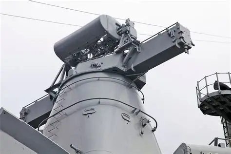
2. Director tracks present position. The Mk 38 director is a trainable, roll-stabilized house on the tower. Crew: pointer, trainer, rangefinder operators, talkers. Optics: pointer and trainer telescopes plus a long-base coincidence rangefinder in the “ears” (Bureau texts: Mark 48 on the Mk 38; some Iowa popular accounts say Mark 45 — treat the Bureau chapter as the director-type source). The director is slaved to stay on the target: as the ship yaws and the target bears off, power drives keep the LOS on the contact.
Radar preferred after it exists. Mk 8 (Western Electric, polyrod array, ~10 cm class, precision range to ~45,000 yd, range accuracy on the order of 15 yd + 0.1% of range, bearing about 2 mils in the OP-658 figures) sits on the flat roof the designers left for a set that was not yet installed when the director was drawn. Late 1945: Mark 13 replaces Mk 8 on most directors — 3 cm, 50 kW, 0.3 µs pulses, PRF 1,800, 8×2 ft dish in a radome, gain ~14,000, beam ~0.9° × 3.6°, “rocking-horse” scan ±5.75° at five cycles each way per second, B-scope to 80,000 yd. Range and bearing go below by synchro. Splash can be seen on the same scope for spots.
What the director transmits continuously: director train (relative bearing), director elevation, present range, and — from its own sensors or from plot — the angles plot needs. Level and cross-level for the system come primarily from the stable vertical in plot, not from a man guessing the roll.
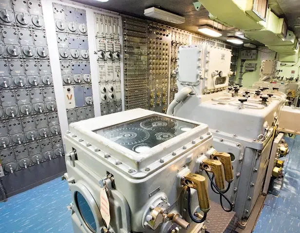
3. Plotting room solves future position. Below the waterline, inside the belt: Mk 8 Rangekeeper (Ford Instrument Company — Hannibal C. Ford, not Detroit), Mk 41 (Iowa) or Mk 43 (South Dakota) Stable Vertical, radar indicators, parallax correctors, fire-control switchboard, battle telephones, battery status, gunnery officers and firecontrolmen (later FTs).
The Mk 8 is an electromechanical analog computer: shafts, differentials, ball-and-disk integrators, ballistic cams. It is a rangekeeper, a bearing keeper, a deck-tilt and trunnion-tilt corrector, and a ballistic computer in one box. It can be hand-cranked if the motor dies. Own course and speed arrive automatically from compass repeater and pit log. Wind from the anemometer. Target motion is generated by integrating observed bearing rate and range rate; the operator watches the generated values against the live director/radar feed and applies corrections when the target zigzags. Time of flight comes out of the ballistic cams for that range, charge, and projectile.
Corrections the cams and resolvers add to the simple “aim ahead” geometry: gravity drop, drift / Magnus, density and temperature (when entered), Earth curvature, Coriolis, relative wind, and the fact that a gun on a tilted, turning turret does not point where a level tangent says. Output: continuous gun train order and gun elevation order (LOF), plus sight angle / sight deflection for local turret sights if the turret must shoot in local or pointer fire.
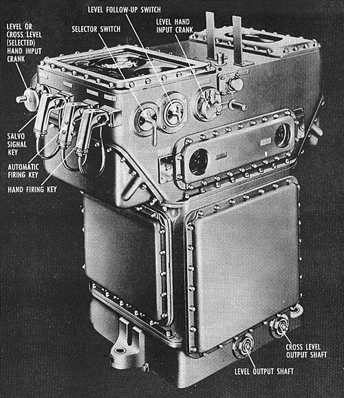
4. Stable vertical defines “up.” The Mk 41/43 is a vertical-seeking gyro. It measures level (tilt in the plane of own-ship heading) and cross-level (tilt across that plane). Those angles go into the rangekeeper — on some installations as rotating shafts rather than synchros, a mechanical marriage unique to this plant. The stable vertical also holds the firing keys for the battery: the salvo is released when the guns are at the computed angle and the ship is at a chosen point in the roll, or in selected continuous fire once the drives are tight enough.
5. Switchboard and parallax. The fire-control switchboard assigns which director and which plot own which turrets. Forward plot can take after director; turrets can be split. Parallax correctors offset each turret’s orders for the horizontal distance between that turret’s trunnions and the director that is tracking — at 30,000 yd the offset is small; at short range against a shore battery it is not.
6. Turret follows. Synchro gun orders arrive at the turret officer’s booth. Receiver-regulators and amplidyne generators turn a few watts of error signal into the horsepower that slews the turret in train and the guns in elevation. The turret is a closed servo: it reports actual train and elevation back so the error goes to zero. Inside, each gun has its own powder hoist, projectile hoist, rammer, and breech. Turret rangefinders (one per turret on the battleships) can feed plot or fight the turret in local control if the director is gone.
7. Shoot, spot, correct. Plot fires the battery. Mk 13 (or optics / aircraft / a destroyer’s report) sees the pattern relative to the target. Range and deflection spots are hand-cranked into the rangekeeper. The next salvo is not a new problem; it is the same running solution with a bias. That loop is why a well-handled Iowa could stay on a maneuvering target at ranges Japanese optics-and-estimate systems lost.
SUPPORTING HARDWARE (THE BOXES THAT ARE NOT “THE DIRECTOR”)
Ford Mk 8 Rangekeeper (Mods 9 or 11 cited for new-construction battleships) — analog computer, hand-crank backup, plotter surface that gave the room its name. Mk 41 / Mk 43 Stable Vertical — gyro “up,” firing keys. Mk 8 then Mk 13 FC radar — Western Electric; transmitters and much of the electronics live below, only the antenna and some indicators ride the director. Mk 27 independent radar appears in some auxiliary-plot descriptions. Auxiliary computers Mk 3 / Mk 6 and auxiliary directors Mk 40 / Mk 55 — standby / secondary control paths listed in the main-battery chapter. Mk 6 stable element — used with those auxiliary computers on some ships. Synchros, IC switchboards, battle telephones — the data bus. Voice tube is the failure mode this plant was built to retire. Amplidyne / receiver-regulator turret drives — the muscle. Without tight servos the computer’s precision is wasted on a turret that hunts. Pitometer log, master gyrocompass, anemometer — own-ship truth data. Turret optical rangefinders — last-ditch and local-control range. 1980s HP digital adjuncts on reactivated Iowas — digital wrap around the still-turning analog shafts.
CREW AND CONTROL MODES
Primary: director + plot in control, turrets in automatic follow. Secondary: after director, or forward director into after plot, if one tower or one room is hit. Local: turret officer uses turret sights and turret rangefinder. Pointer fire: men on the pieces. The switchboard is how the gunnery officer picks the mode without rewriting the ship.
Rates in the director and in plot were firecontrolmen. The rating badge is a rangefinder and lightning bolts for a reason.
LIMITS
Surface problem first. AA against aircraft is the Mk 37 plant’s war. Mk 13 is a sector-scanning FC radar, not a modern track-while-scan illuminator; one director, one tight track. Analog cams are built for a family of projectiles and charges; a new shell means new metal or a paper correction. First-salvo hit probability still depends on the opening rates guess. A director that cannot see (blast damage, power, ice on the RF) falls back to turret optics or another director.
CAVEATS
Rangefinder mark (48 vs 45) disagrees between Bureau chapter and some Iowa secondary pages. Radar range figures are OP and NavSource summaries, not a live calibration sheet. “Best in the war” is a U.S. claim measured against Japanese systems that were optically excellent and radar-poor; it is not a statement that every salvo landed. Production and exact mod lists for every hull sit in BuOrd records this page does not reproduce.
STATUS
Out of commission with the battleships. Museum Iowas still show Mk 38 directors, Mk 13 antennas, and Mk 8 rangekeepers. The modern Mk 38 25 mm / 30 mm Mod 4 line is a different weapon with the same number.
IN ONE SENTENCE
The Mark 38 GFCS is the U.S. fast-battleship main-battery plant — Mk 38 director and Mk 8/13 radar aloft, Ford Mk 8 rangekeeper and Mk 41/43 stable vertical in armored plot, synchro-and-amplidyne orders to the 16-inch turrets — that continuously aims heavy guns at a moving target from a rolling ship.