WHAT IT IS
A CT scanner (computed tomography, also called CAT scan) is an X-ray machine that takes hundreds to thousands of projection images of a body from many angles and uses a computer to reconstruct them into cross-sectional images (slices) and 3D volumes. The word comes from Greek tomos (slice) and graphein (to write). A plain X-ray flattens the whole body onto one picture, so a rib, a lung nodule, and the spine all overlap. CT removes the overlap: each voxel (3D pixel) in the output is a number that says how strongly that tiny block of tissue weakens the X-ray beam.
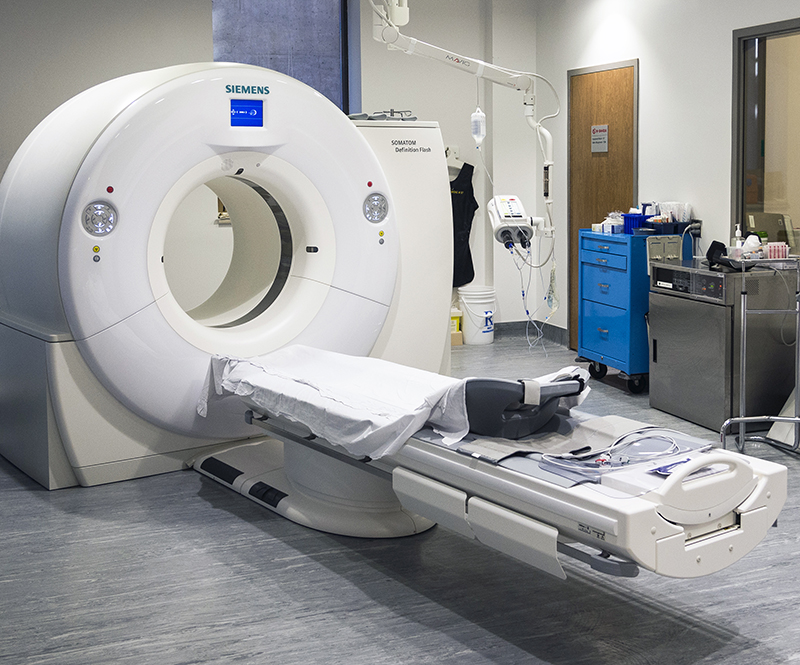
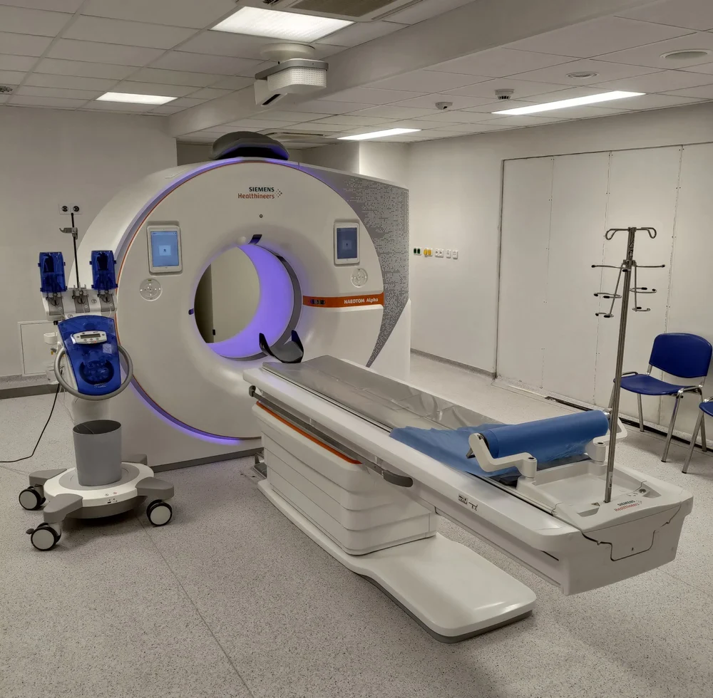
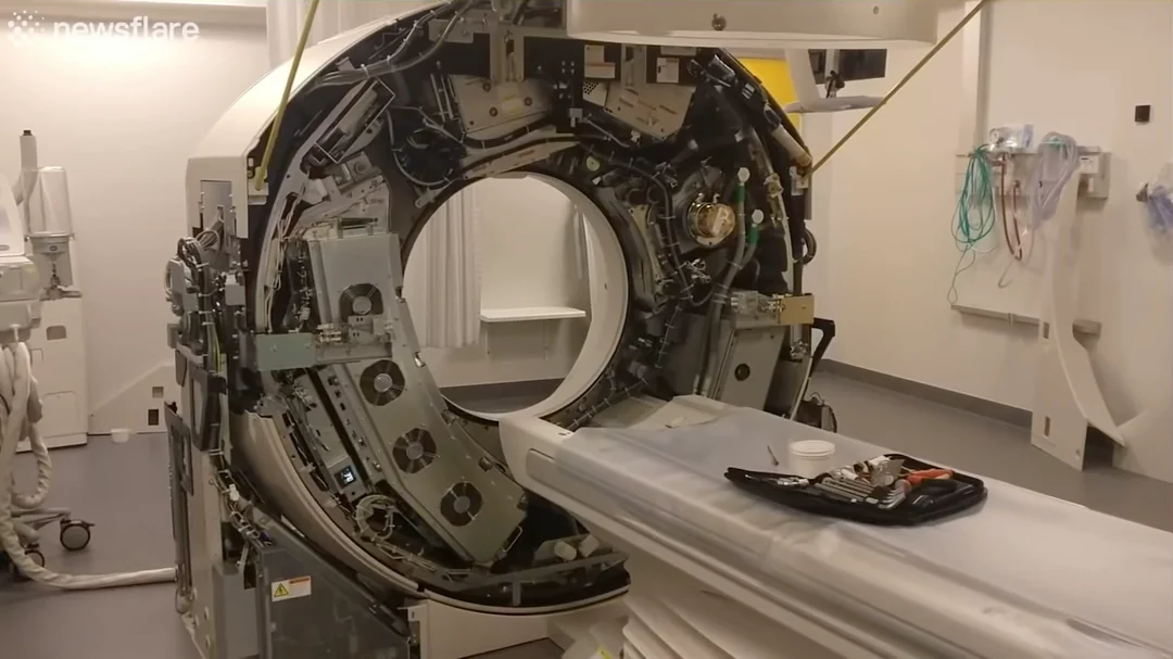
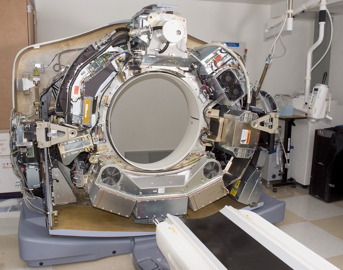
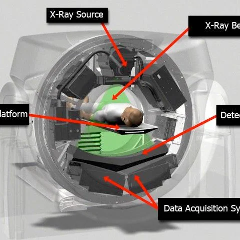
The machine is a large ring called the gantry with a bore (opening) usually 70 to 90 cm across, and a motorized patient table that slides the patient through it. Inside the gantry, an X-ray tube and a curved array of detectors sit on opposite sides of the bore and spin together around the patient. A complete modern head or chest exam is a few seconds of actual X-ray time. Most hospitals of any size have at least one, and trauma centers and emergency departments depend on them for fast diagnosis.
CT is a structural imaging method. It shows density and shape: bone, air, fat, fluid, calcium, blood, contrast-filled vessels, tumors. It does not directly show function in the way PET does, and it has less soft-tissue contrast than MRI, but it is fast, widely available, tolerant of patients who cannot lie still for long, and works with metal implants that rule out many MRI exams.
HISTORY
Mathematical roots. In 1917 the Austrian mathematician Johann Radon proved that a function in two or three dimensions can be recovered from the integrals of that function along lines through it (the Radon transform). That is the math behind CT, though it had no practical use in 1917. The South African-born physicist Allan MacLeod Cormack independently worked out the problem for X-ray attenuation in the early 1960s and published his results in 1963 and 1964. William Oldendorf did a laboratory demonstration of reconstruction in 1961 using a rotating model.
Hounsfield and EMI. The English electrical engineer Godfrey Newbold Hounsfield, working at EMI's Central Research Laboratories in Hayes (the same company known for The Beatles' records), built the first working clinical CT scanner. His early lab prototype used a gamma source and took days to acquire data; an X-ray version cut that to hours and then minutes. The first patient scan was done in October 1971 at Atkinson Morley's Hospital in Wimbledon, London; it showed a cystic frontal-lobe brain lesion. Hounsfield and the radiologist James Ambrose presented the results in April 1972, and the scanner was announced publicly later that year. The EMI Mark I was head-only. Its image was an 80 × 80 matrix, and one slice took about 5 minutes to scan, followed by long computer reconstruction. Hounsfield and Cormack shared the 1979 Nobel Prize in Physiology or Medicine.
Whole-body CT. The first whole-body scanners appeared in 1974-1976, including the ACTA scanner by Robert Ledley at Georgetown University and the EMI CT5000 whole-body unit. From there the field moved fast, and EMI's lead evaporated once GE, Siemens, Philips and Toshiba entered. EMI left the CT business by the early 1980s.
GENERATIONS OF SCANNER GEOMETRY
HOW IT WORKS: THE CHAIN
In order, a scan runs through this chain: tube generates X-rays, filter and collimator shape the beam, the beam passes through the patient, detectors measure what gets through, the data acquisition system digitizes it, a slip ring carries the data off the spinning gantry, and a reconstruction computer turns it into images.
THE X-RAY TUBE
The tube is a vacuum glass or metal envelope with a heated tungsten filament (cathode) that boils off electrons, and a rotating anode target that the electrons are accelerated into by a high voltage. Typical CT tube voltages are 70 to 150 kVp (kilovolts peak), with 80, 100, 120 and 140 the standard choices; 120 kVp is the common default for adult body imaging. Tube current is typically tens to several hundred milliamperes, and the highest-end tubes go beyond 1000 mA for large patients and fast scans. Peak generator power is often in the range of roughly 60 to 120 kW for modern units.
Less than 1 percent of the electron beam energy becomes X-rays; the rest becomes heat in a focal spot only a millimeter or so across. To survive, the anode is a disk of tungsten-rhenium alloy on a molybdenum or graphite body (graphite stores heat) spinning at roughly 7,000 to 10,000 rpm (about 150 Hz) so the focal track is constantly renewed. The key CT tube spec is anode heat storage, measured in MHU (million heat units); typical values on current tubes are about 5 to 8 MHU, with anode cooling rate in kHU per minute being equally important because it sets how long a series of scans can continue without a cooldown wait. Some designs (Siemens Straton and later) are rotating-envelope tubes where the whole tube spins and the anode is cooled directly by oil in contact with its back; others use liquid-metal (gallium-alloy) bearings and a conventional anode. These cope with the mechanical load of the gantry.
The gantry's rotation puts enormous force on the tube. At roughly 0.25 to 0.28 seconds per revolution and a tube radius of about 0.6 m, centripetal acceleration works out to the order of 30 g (approximate, calculated from those numbers). That is why tubes and detector modules are built as heavy, balanced, rigid assemblies, and why bearing failure and imbalance are real service concerns.
FILTRATION AND COLLIMATION
The tube produces a spectrum from low to high energy photons. The low-energy photons would be absorbed by the first few centimeters of the patient and add dose without contributing to the image, so the beam is filtered with aluminum, copper or other metal plates (total filtration at least about 2.5 mm aluminum equivalent in regulation). A bow-tie filter, a shaped piece thicker at the edges than at the center, flattens the beam intensity after it passes through a round patient and further reduces dose at the skin. Siemens introduced a selectable tin pre-filter on some systems to narrow the spectrum for low-dose lung and sinus protocols. Collimators (metal shutters) define the width of the beam along the body axis, which sets the slice thickness and the coverage and keeps scatter and dose down. A second set of collimating grids on the detector faces rejects scattered photons.
DETECTORS
Almost all clinical CT scanners built until recently use indirect-conversion (scintillator) detectors: X-rays hit a scintillator crystal or ceramic, commonly a rare-earth ceramic such as gadolinium oxysulfide (GOS) or a garnet (GE Gemstone), cesium iodide in some designs, that glows; a photodiode behind it turns the light into a current. The detector arc has several hundred to well over 800 channels across the fan and 16 to 320 rows along the body axis, in modular cassettes. Indirect detection loses some signal in the light conversion and the septa between pixels.
Direct-conversion detectors use a semiconductor such as cadmium telluride (CdTe) or cadmium zinc telluride (CZT), in which each X-ray photon directly creates a cloud of electron-hole pairs that a high bias voltage sweeps to pixel electrodes. In a photon-counting detector the pulse height is proportional to photon energy, so each photon is counted and sorted into energy bins. Benefits: no electronic noise floor in the counting, no septa needed and so smaller pixels and sharper images (the NAEOTOM Alpha offers an ultra-high-resolution mode with details to about 0.2 mm), inherent spectral information on every scan, and better contrast-to-noise at low dose. The difficulties are pile-up at high flux, crystal defects and charge sharing, and expensive crystals, so these detectors came to market decades after they were first proposed. Philips offers an alternative, the dual-layer "sandwich" detector (a top layer that absorbs low-energy photons and a bottom layer that gets the rest), which is still a scintillator system.
DATA ACQUISITION AND SLIP RINGS
Each detector channel's analog signal is integrated over short intervals (thousands of views per rotation, typically around 1,000 or more), digitized by the data acquisition system (DAS) mounted on the gantry, and sent off the spinning part as a high-speed digital stream (multiple gigabits per second on modern units) via the slip ring or an optical or capacitive link. The slip ring is a set of conductive rings with brushes (or contactless couplings) that pass power up to the rotating assembly and carry data back. Replacing cables with slip rings is what made continuous rotation and helical CT possible.
PATIENT TABLE
The table is a carbon-fiber top (strong, light, and nearly transparent to X-rays) on a motorized base. It moves in and out of the gantry with sub-millimeter positioning accuracy and carries patients up to roughly 200 kg or more depending on model (bariatric tables go up to about 300 kg on some systems, per manufacturer specs). In helical mode the table speed is synchronized with the gantry. The table can also raise and lower, and the gantry can tilt on some scanners.
PHYSICS: HOW AN IMAGE IS BUILT
Attenuation (Beer-Lambert law). A monochromatic beam of intensity I0 passing through a uniform material of thickness x and linear attenuation coefficient μ comes out with intensity I = I0 e-μx. For a non-uniform body, the measurement along one ray gives the line integral of μ, i.e. ln(I0/I) = ∫ μ(s) ds. Each detector reading in each view is one such line integral (a projection value). The collection of all of them over all angles is a sinogram, and reconstruction means recovering μ(x,y) from it. Real X-ray beams are polychromatic, which causes the artifacts discussed below.
Hounsfield units. The reconstructed attenuation values are scaled so that water is 0 and air is -1000: HU = 1000 × (μ - μwater) / (μwater - μair). Typical values at about 120 kVp (approximate and they vary by scanner, kVp and patient):
Reconstruction. The classic method is filtered back projection (FBP): each projection is convolved with a ramp-like filter (the kernel) to compensate for the blurring that simple back projection causes, and the filtered projections are smeared back across the image at their original angle and summed. FBP is fast and was the clinical standard for decades. Its weakness is noise at low dose. Since about 2008-2010 vendors introduced iterative reconstruction (GE ASiR and Veo, Siemens IRIS, SAFIRE and ADMIRE, Philips iDose and IMR, Canon AIDR 3D and FIRST). These loop between an image estimate and a model of the scanner's physics and noise, repeatedly refining the image; they allow roughly 30 to 60 percent or more dose reduction at similar image noise depending on the algorithm and task. Since about 2018-2020 deep-learning reconstruction has arrived (GE TrueFidelity, Canon AiCE, Siemens' neural-network-based tools, Philips Precise Image), in which a neural network trained on high-dose images is used to denoise or reconstruct low-dose data. For cone-beam geometry, the FDK (Feldkamp-Davis-Kress) algorithm is the standard approximation.
Windowing. The monitor cannot display the whole -1000 to +3000 HU range in 256 gray levels, so the radiologist picks a window level (center) and window width. A brain window is something like level 40, width 80; a lung window about level -600, width 1500; a bone window about level 400, width 1800 or more; an abdomen soft-tissue window about level 40, width 400. The same data reveal totally different things in different windows.
Pitch, slice thickness and resolution. In helical scanning, pitch is the table travel per gantry rotation divided by the total beam collimation width. A pitch of 1 means contiguous coverage; below 1 overlaps (more dose, better sampling), above 1 gaps (faster, less dose, interpolation). Dual-source scanners in a special fast mode can use pitch up to about 3.2 to 3.4 (Siemens specs for Flash and Force) to freeze the heart or image a child without sedation. Slice thickness is set by the detector row width and the reconstruction; modern scanners acquire submillimeter data (commonly 0.5 to 0.625 mm) and reconstruct thicker slices for routine reading. Spatial resolution in the plane is typically about 0.3 to 0.5 mm in the best conventional systems and about 0.2 mm in photon-counting ultra-high-resolution modes, and nearly isotropic in the z-axis. Temporal resolution is about half the rotation time in single-source scanners (around 135 to 140 ms for 0.27 to 0.28 s rotation), and about a quarter in dual-source (66 to 75 ms). That is the difference between a blurred and a sharp coronary artery. Low-contrast resolution (the ability to see small differences in HU against noise) is limited by dose and noise, and is why CT is weaker than MRI for soft tissue.
Gantry rotation speed. Fastest commercial rotation times are about 0.25 s (Siemens Force and NAEOTOM Alpha), 0.27 s (Canon Aquilion ONE Prism, approximately) and 0.28 s (GE Revolution series). Mechanical limits and the g-force on the tube set the floor.
CONTRAST AGENTS
Natural CT contrast between soft tissues is small, so most body CT is done with iodinated contrast injected into a vein (usually through a power injector at roughly 2 to 5 mL per second, with total volumes around 50 to 150 mL, concentrations of roughly 300 to 370 mg iodine per mL). Iodine has a high atomic number and a K-edge at 33.2 keV, so it absorbs diagnostic X-rays strongly; a vessel or highly vascular tumor lights up white. Current agents are non-ionic, low- or iso-osmolar: iohexol (Omnipaque), iopamidol (Isovue), iodixanol (Visipaque), iopromide (Ultravist), ioversol (Optiray). Timing matters: arterial phase for angiography, portal-venous phase (about 60 to 70 s) for most abdominal work, delayed phase for the urinary tract or washout. Bolus tracking watches an artery's HU and triggers the scan when it hits a threshold. Oral contrast (dilute iodine or barium) is sometimes given to light up the bowel, and rectal or intra-articular contrast is used for specific studies. Non-contrast CT is the default for stroke bleeds, kidney stones and many lung and bone questions.
Risks. (1) Allergic-like reactions: mild ones (hives, itching, nausea) occur in roughly 0.5 to 3 percent of injections with modern low-osmolar agents (estimates vary), and severe reactions are rare (on the order of 0.01 to 0.04 percent). Prior reaction raises risk; premedication protocols exist. It is not a true iodine or seafood allergy. (2) Kidney effects: contrast-associated acute kidney injury is uncommon in patients with normal kidney function; current ACR and National Kidney Foundation consensus (2020) puts the real risk mainly in patients with eGFR under 30 mL/min/1.73 m² or acute kidney injury, and screening focuses on those patients. Hydration is the main preventive measure. (3) Extravasation, when contrast leaks out of the vein into the surrounding tissue, which is usually minor but can cause tissue injury in large volumes. (4) Interaction with metformin, which guidelines handle by kidney function. (5) Thyroid effects in susceptible patients (iodine load). Pregnancy and lactation have their own guidance. A technologist or radiologist screens every patient for these.
RADIATION DOSE
CT is a high-dose X-ray modality compared with plain films, and it accounts for a large share of the medical radiation received by the population in developed countries. Doses are quoted as CTDIvol (mGy, scanner output), DLP (dose-length product, mGy·cm) and an effective dose in millisievert (mSv) estimated as DLP times a body-region conversion factor (roughly 0.002 for head, 0.014 for chest, 0.015 for abdomen/pelvis mSv per mGy·cm). Effective dose is a population-risk tool, not a precise individual measurement. Typical adult values (approximate and highly dependent on scanner, protocol and patient size):
The principle is ALARA (as low as reasonably achievable): scan only when the clinical question justifies it, and use the lowest dose that answers it. Scanners reduce dose with automatic exposure control (tube current modulation by patient size along the z-axis and by angle during the rotation), ECG-based dose modulation in cardiac CT, prospective ECG triggering, lower kVp for small patients and contrast studies, tin filtration, iterative and AI reconstruction, organ-dose modulation (reduced exposure over the breasts, eyes), and size-specific protocols for children (Image Gently campaign). The cancer risk from a single CT is small and difficult to measure directly; epidemiological estimates are mostly extrapolated from atomic-bomb survivor data using a linear no-threshold model, which is debated. The risk is higher in children because of longer remaining lifespan and more sensitive tissue.
WHAT CT CAN DETECT
What CT is poor at: subtle soft-tissue differences (small brain tumors, spinal cord, ligaments, early ischemia), small bowel and pelvic organ detail, and function (metabolism) which needs PET or SPECT. PET/CT and SPECT/CT combine a CT scanner with a nuclear camera so the CT supplies the anatomy and attenuation correction.
CT VERSUS MRI, X-RAY AND ULTRASOUND
LIMITS AND ARTIFACTS
CONE-BEAM CT, INDUSTRIAL AND SECURITY CT
Cone-beam CT (CBCT) uses a flat-panel detector (a 2D array, as in digital X-ray) and a cone-shaped beam, and acquires a whole volume in a single rotation of the source around the patient or object, with no table movement. It is used in dentistry and oral surgery (compact scanners with a seated or standing patient), ENT, C-arm angiography suites (intraoperative 3D imaging), and radiation therapy linacs (image-guided radiotherapy, IGRT, for positioning the patient before treatment). Its image quality for soft tissue is lower than a multi-slice CT, and Hounsfield values are less reliable because of scatter, but the machines are smaller, cheaper and lower dose for the specific tasks.
Industrial CT scans manufactured parts to find internal voids, cracks, porosity in castings, weld flaws and assembly errors, and to measure internal geometry (metrology) without cutting. Micro-CT reaches micron-scale resolution for electronics, small biological specimens, fossils and materials research. Industrial systems often use the specimen rotating in a fixed beam, with tube voltages from tens of kV up to 450 kV or more, and linear accelerators of several MeV for large castings and rocket motors.
Security CT is used to screen luggage. Explosive-detection systems (EDS) in airports use CT to compute the density and effective atomic number of objects in bags and flag possible explosives, and in recent years the TSA and European airports have rolled out CT scanners at passenger checkpoints so that laptops and liquids may stay in bags (details vary by airport and rules change over time). Vendors include Smiths Detection, Rapiscan (OSI), Analogic and Leidos.
POWER, INSTALLATION AND ROOM
The figures below are typical and approximate. The manufacturer's site planning guide and a qualified medical physicist control the actual requirements for any given scanner.
MAINTENANCE AND FAILURE POINTS
MANUFACTURERS AND CURRENT MODELS
The market for hospital-grade CT is dominated by a handful of firms. Model names change, so treat the lists below as examples and check the maker for current line-ups.
Key performance classes (approximate): entry scanners 16 to 64 slices at 0.4 to 0.5 s rotation; mainstream 64 to 128 slices at 0.33 to 0.35 s; premium 128 to 320 rows at 0.25 to 0.28 s; dual-source at 0.25 s with 66 to 75 ms temporal resolution; photon-counting at 0.25 s with 66 ms and ultra-high-resolution mode. The scanner in the first photo is a Siemens SOMATOM Definition Flash-class dual-source system and the second shows a NAEOTOM Alpha photon-counting scanner.
SAFETY NOTE
This page is a technical reference, not medical advice. Whether a CT scan is needed for a given person is a decision for their doctor, who weighs the diagnostic benefit against the dose.
IN ONE SENTENCE
A CT scanner spins an X-ray tube and a detector arc around the patient, measures how much each ray is attenuated from thousands of angles, and reconstructs those line integrals into a 3D map of Hounsfield-unit densities, in seconds, at a dose of roughly 1 to 10 mSv: the fastest, most widely used way to look inside the body for bleeds, clots, stones, fractures and tumors.