WHAT IT IS
A cathode-ray tube (CRT) is a vacuum bottle that paints a picture with a steered beam of electrons. A hot cathode boils electrons off a nickel cap. Grids and anodes form those electrons into a pencil. Magnetic coils or electrostatic plates sweep the pencil across a phosphor-coated face. Where the beam hits, the phosphor flashes. Persistence of the phosphor plus persistence of vision turn a flying spot into a line, a raster, a scope trace, or a television frame.
It is an analog computer output that happens to be visible. Intensity is beam current. Position is deflection current or plate voltage. There is no native pixel grid on a monochrome tube. Color tubes impose a grid with a shadow mask or aperture grille so three guns can only light their own phosphor.
HOW THE BEAM IS MADE
Heater and cathode. A tungsten heater, typically 6.3 V at a few hundred milliamps (some guns 1.5 V / ~140 mA), sits inside a nickel cathode sleeve. The emitting face is a barium/strontium oxide coating. Heat ~700–800 °C. Thermionic emission. The cathode sits near ground or a few tens of volts; the screen sits at the anode potential, so the electrons fall through 10–32 kV.
Wehnelt / G1. A cup with a pinhole, biased negative to the cathode (tens of volts). That voltage is brightness. More negative, fewer electrons through the hole. Cutoff kills the beam.
G2 / accelerator. A few hundred volts to a kilovolt. Pulls the beam out of the Wehnelt and starts the pencil.
Focus (G3 / A1). Electrostatic einzel or bipotential lens, or a magnetic focus coil on radar/oscilloscope tubes. Focus voltage on consumer color sets is typically a few kV derived from the flyback; cheap einzel guns used 0–600 V. The lens images the crossover onto the phosphor as a spot a fraction of a millimetre across.
Final anode. The inner graphite (Aquadag) and the aluminium film behind the phosphor are the anode: ~15–21 kV on many mono / instrument tubes, ~24–32 kV on large color television and monitor tubes. Glass formulation sets the safe ceiling; color glass is thicker and leaded for X-ray absorption. At 10 kV the electrons are already ~60,000 km/s class; at 25 kV they are a substantial fraction of that. Kinetic energy dumped into the phosphor is light plus heat plus a little X-ray.
A color tube is three of these guns in one neck — delta or in-line — aimed through the same yoke.
HOW THE BEAM IS STEERED
Electrostatic deflection (oscilloscopes, some radar and military HUDs): two pairs of plates, X and Y. Voltage on the plates bends the beam. Fast. Limited deflection angle, so the tube is long. Bandwidth of a good analog scope is the plate driver, not a raster chip.
Magnetic deflection (television, computer monitors, most PPI radars): a yoke of saddle or toroidal coils on the flare of the funnel. Horizontal coil driven by a sawtooth of several amps at line rate (15.734 kHz NTSC, 15.625 kHz PAL, 31–100+ kHz on multisync monitors). Vertical coil at field rate (50/60 Hz, or 70–120 Hz on computer CRTs). The flyback transformer that dumps the horizontal coil also makes the anode high voltage. That is why a dead HOT (horizontal output transistor) kills both sweep and high voltage.
Geometry is not free. Pincushion, barrel, trapezoid, and (on color) convergence — red, green, and blue landing on the same triad — are corrected by extra coils, magnets on the neck, and analog networks or a digital convergence box on late Sony / NEC / Barco gear.
THE SCREEN
Phosphor on the inner face, then a thin aluminium mirror that throws light forward and conducts anode current. Phosphor type is a military/industrial catalogue: P1 green medium persistence, P4 white TV, P7 two-layer radar (blue flash, yellow-green afterglow), P11 blue photo, P22 RGB color TV, P31 fast green scopes, P39 long-persistence radar, and dozens more. Decay time is the motion-blur number that LCD vendors still chase: many display phosphors fall to 10% in well under a millisecond; some radar phosphors glow for seconds.
Monochrome: continuous phosphor. Resolution is spot size and focus, not a factory pixel map.
Shadow-mask color (RCA Law, 1950s): a formed steel sheet 0.10–0.25 mm thick, 10 mm or so off the glass, punched with 200,000–400,000 holes or slots. Each hole is the aperture for one RGB triad. The three beams approach at slightly different angles; the mask shadows two phosphors and passes the third. Pitch 0.20–0.28 mm was “high res” on late computer CRTs; TV masks were coarser.
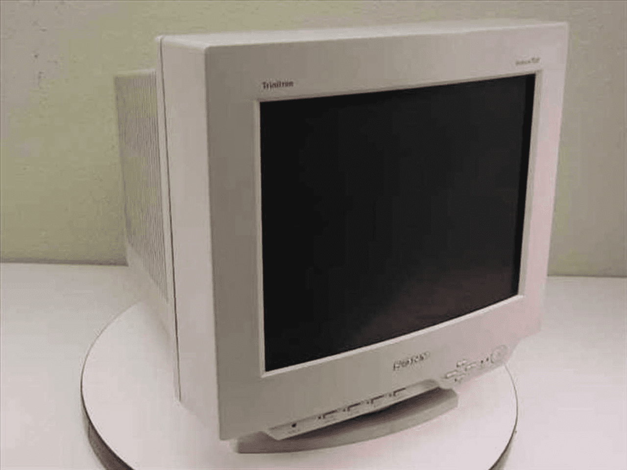
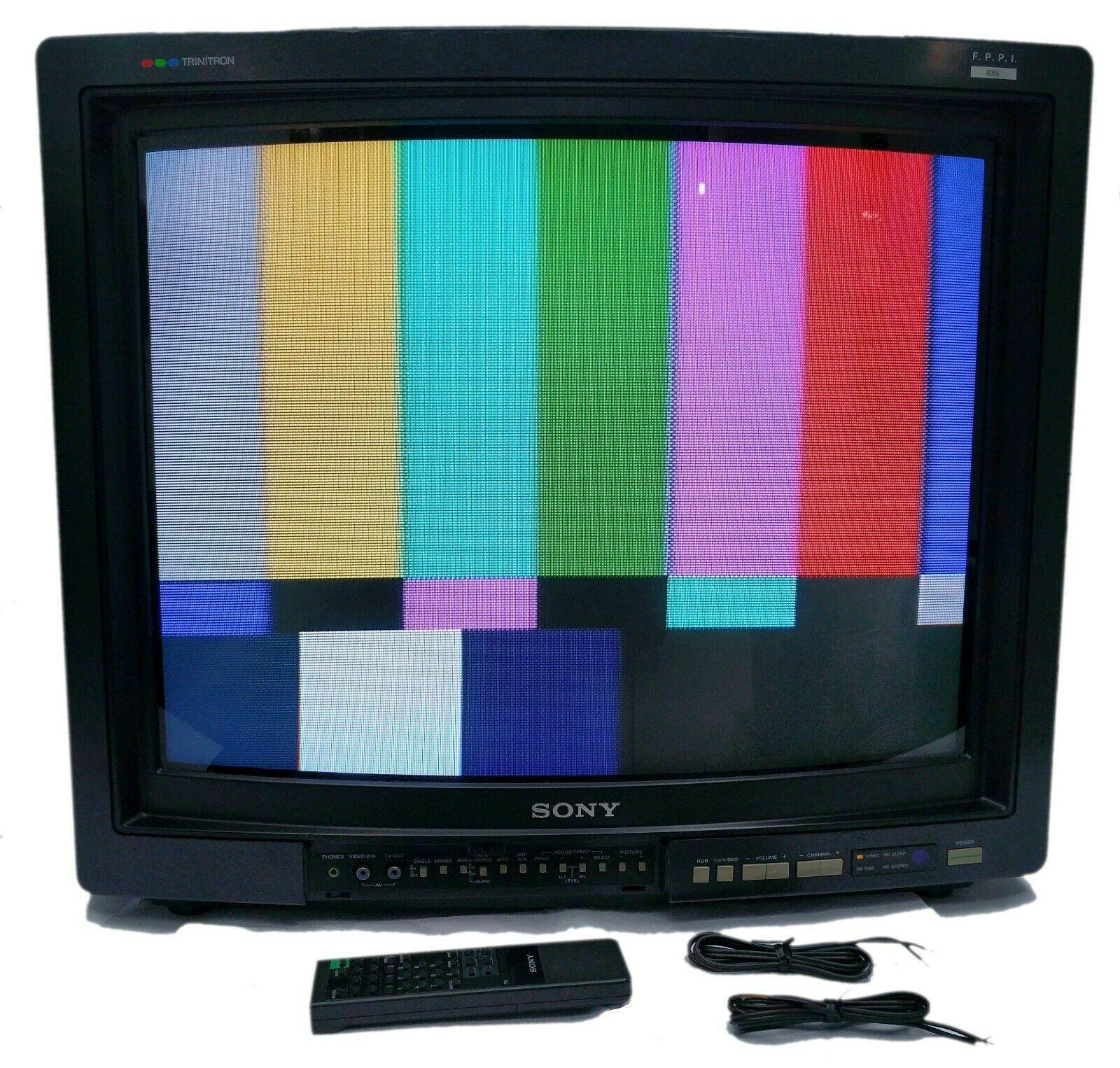
Aperture grille (Sony Trinitron and cousins): vertical tungsten wires instead of a hole plate. Phosphor is stripes. Tensioned by damper wires. Higher transmission (brighter), cylindrical face on classic Trinitrons, different moiré and purity behavior. Same three-gun idea.
Beam current that misses the hole hits the mask and heats it. A hot mask expands and the color goes dirty — purity drift — until the tube is degaussed and the mask settles.
HOW THE BOTTLE IS BUILT
1. Press or spin the faceplate and the funnel from leaded or barium glass. Embed the anode button. Apply the implosion band (tensioned steel rim) later — a 27-inch color tube is holding ~1 atmosphere on a square metre of glass.
2. Screen: slurry or slurry-plus-photolith the phosphor. For color, coat, expose through the actual mask, wash, repeat for R, G, B. Aluminize.
3. Seal the mask or grille to the face panel. Frit-seal panel to funnel.
4. Mount the gun on a glass stem with pins. Seal the neck. Evacuate, bake, getter-flash (barium mirror) to mop residual gas. The vacuum is the product.
5. Paint inner and outer Aquadag. The two coatings plus the glass are a capacitor that stores the anode charge — that is the shock in the anode cap after unplug.
6. Yoke, purity magnets, convergence assembly, socket. Age the cathode. Align.
Military and radar tubes add aluminized shields, bonded implosion panels, extra gun ruggedizing, and sometimes a fiber-optic faceplate for film or scan conversion.
DRIVE ELECTRONICS
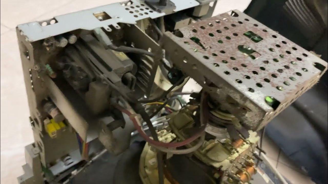
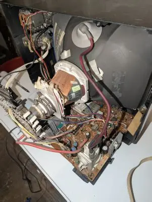
Video amp on the neck board, bandwidth tens to hundreds of MHz on a good monitor. Horizontal output + flyback + damper diode. Vertical output IC or discrete. Low-voltage rails. Degauss coil and posistor. For color, three video amps and a cutoff/bias setup so the guns track. Oscilloscopes skip the raster and drive the plates from the timebase and vertical amp. PPI radars sweep the yoke in polar coordinates — rotation plus range sweep — instead of a TV raster.
Interlace (480i, 576i) is a bandwidth cheat: two fields make one frame. Computer CRTs went progressive at 70–85 Hz and higher to kill flicker. A CRT can run any timing the yoke and flyback will stand; that is why a multisync VGA monitor accepted 640×480 through 1600×1200 from one tube.
WHAT IT WAS USED FOR
Television. Computer monitors. Oscilloscopes. Radar PPI and A-scopes (including every Cold War CIC and SPRN-era console that was not a later LCD retrofit). Aircraft HUDs and some helmet sights. Film recorders. Vector arcade and calligraphic CAD. Medical fluoro. Oscillographs. The analog world needed an analog spot.
CRT vs LCD / LED-BACKLIT LCD / OLED
Motion. CRT advantage. The phosphor is a flash, then dark. Sample-and-hold LCD holds the frame for the whole interval; the eye tracks and smears. OLED is faster than LCD but still a hold-type display unless pulsed. Strobe backlights (ULMB / ELMB / DyAc) imitate the CRT flash and pay in brightness and flicker. CRT motion clarity at 60–85 Hz still beats a non-strobed 144 Hz LCD for many eyes.
Black and contrast. A CRT can shut the beam off. Real black, in a dark room, is excellent. Quoted static contrast of 200–300:1 underestimates what a well-set tube looks like because the measurement includes glass reflection. LCD contrast is backlight leak plus polarizer; mini-LED local dimming and OLED close the gap, OLED winning on per-pixel black.
Color and viewing angle. CRT phosphors are wide-gamut enough and Lambertian. You can sit off-axis and the picture does not go black or invert the way a twisted-nematic LCD does. IPS LCD and OLED fixed the angle problem; cheap TN did not.
Resolution and geometry. Mono CRT: no fixed pixel grid. Color CRT: mask pitch is the pixel. LCD/OLED: the grid is the image. Scaling on a CRT is analog and soft; scaling on a panel is a discrete resample. A CRT does not have a native 1920×1080. It also bows, blooms when the beam is too hot, and needs convergence.
Input lag and timing. A CRT displays the line as it arrives. No scaler frame buffer unless you add one. That is why light-gun games and some radar operators still want tubes. Modern LCD/OLED almost always buffer at least a frame.
Size, weight, power. LCD/LED win without argument. A 21-inch CRT is a 20–30 kg implosion vessel plus a 30 kV supply. Power is tens to hundreds of watts. Depth is the tube length. LCD is a pane and a backlight driver.
Burn-in and life. CRT phosphors burn. Radar P7 and OSD status lines prove it. Cathodes lose emission (thousands to tens of thousands of hours; 20k hours is a common brochure). LCD backlights age and yellow; OLED organic stacks burn and lose blue first. Different failure, same eventual dim picture.
Flicker and emissions. 60 Hz CRT flicker is real for a fraction of viewers; 85 Hz fixed most of it. The tube also throws stray magnetic field and a little soft X-ray; later sets were hard-regulated under TCO / MPR. LCD PWM dimming is a different flicker. OLED PWM at low brightness is another.
Environment. CRT likes a wide temperature box and does not care about sunlight as much as a transmissive LCD without a strong backlight — but the face reflects. LCD hates extreme cold until the fluid thickens. OLED hates heat and humidity over years.
Service. A CRT chassis is discrete and schematic-friendly: caps, HOT, flyback, neck board. A modern panel is a T-con board and a bonded stack you do not repair. That is why radar and industrial CRTs lasted in racks after the living-room tube died.
WHY THE TUBE LEFT
Not because the picture was worse. Because the bottle would not go thin, light, cheap, or 50 inches. LCD industrialised. Computer OS UIs assumed square pixels. Broadcast went digital and 16:9. The last mass computer CRTs left the line in the mid-2000s; specialty and military tubes lingered. Oscilloscope and radar CRTs still exist as new-old stock and as rebuilt guns. The physics did not expire.
CAVEATS
Anode voltages and mask pitches are bands, not one part number. “0.01 ms response” for CRT is phosphor rise/fall, not a GtG LCD spec — do not treat the numbers as the same instrument. Contrast ratios in comparison tables mix methods. Trinitron is an aperture grille, not a shadow mask.
STATUS
Consumer production dead. Remaining demand: vintage computing, broadcast mastering nostalgia, some airborne and naval displays not yet redesigned, oscilloscope/radar rebuild. LCD, mini-LED LCD, and OLED own the pane. The CRT owns the explanation of what a scanning spot is.
IN ONE SENTENCE
A CRT is a vacuum electron-gun and phosphor bottle that draws pictures with a steered beam — analog, fast, heavy, high-voltage — still unmatched on motion and true black, displaced by LCD and OLED because glass, 30 kV, and 25 kilograms lost to a flat panel.